Telescopic numerical control cutter frame

A tool rack and connecting plate technology, which is applied in the direction of manufacturing tools, tool storage devices, metal processing machinery parts, etc., can solve the problems of low space utilization, limited capacity of placing plates, inconvenient use, etc., and achieve easy to take and store, Ease of use and increased capacity

Inactive Publication Date: 2018-03-20
常州法蒙精密机械有限公司
View PDF0 Cites 1 Cited by
  • Summary
  • Abstract
  • Description
  • Claims
  • Application Information

AI Technical Summary

Problems solved by technology

[0003] The traditional tool holder has a single structure, simply overlapping the placement boards, setting placement holes on the placement boards, the placement boards are not retractable, and the capacity of the placement boards is limited, so it is not possible to place multiple tools on the same tool holder. It cannot provide all types of knives during use, which is inconvenient to use. At the same time, the space utilization rate of ordinary tool racks is low. When the tool racks are placed in the warehouse, they occupy a large area, which is not conducive to the storage of tool racks.

Method used


Image

  • Telescopic numerical control cutter frame
  • Telescopic numerical control cutter frame
  • Telescopic numerical control cutter frame

Examples


Embodiment 1

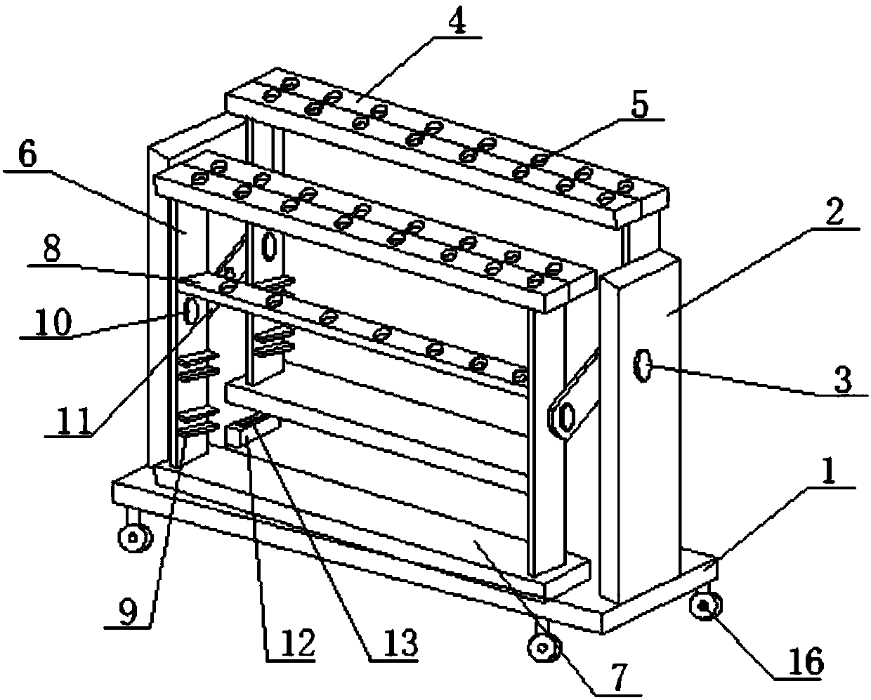
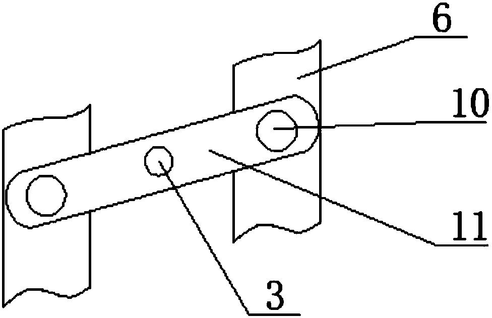
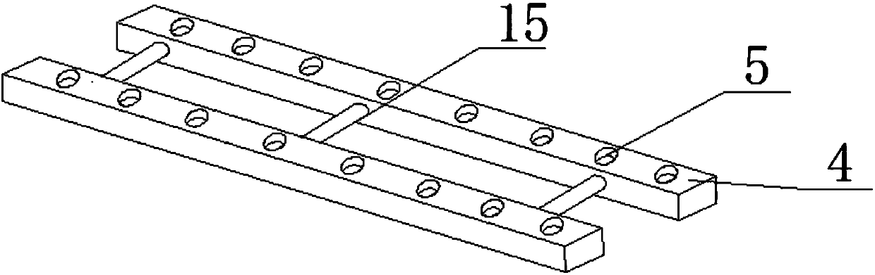
[0022] see figure 1 and figure 2 As shown, a telescopic CNC tool holder includes a base 1, a placement beam 4 and a placement hole 5, the base 1 is connected to a support plate 2 for supporting the device, and a center pin 3 is set at the center of the support plate 2 for easy balance Placement beams 4 on both sides, placement holes 5 are set on the placement beams 4 for placing tools, placement beams 4 are connected to the connection plate 6, connection plate 6 is connected to the bottom plate 7, and the upper end of the connection plate 6 is connected to the beam 8, and more Strengthen the fixation of the tool at the same time, increase the overall stability of the device, a splint 9 is provided at the bottom of the connecting plate 6, and is used to place a movable connecting plate to increase the space for accommodating the tool, and a movable pin 10 is set in the middle of the connecting plate 6, The movable pin 10 is connected with the balance beam 11, which is used to...

Embodiment 2

[0024] In addition, refer to figure 2 , image 3 and Figure 4 , based on the above-mentioned embodiment, a symmetrical support plate 2 is arranged on the base 1, and the support plate 2 is vertically and parallelly arranged so that the device can be supported stably. The center pin 3 is arranged at the center of the support plate 2 on both sides. 3 Corresponding settings, so that the force on both sides is balanced, and it is convenient for the placement beams 4 on both sides to move up and down. The placement beams 4 are movable settings, and the placement beams 4 on both sides can be separated freely. 5. Make the placement beam 4 able to place a more correct tool and facilitate the taking of the tool. A single row of placement holes 5 is set on the cross beam 8. The placement holes 5 are uniformly arranged. The cross beam 8 and the connecting plate 6 are fixedly connected, so that the cross beam 8 is connected It is firmer, and the connection between the connecting plate...


PUM


Abstract

The invention discloses a retractable numerical control tool holder, which belongs to the field of mechanical processing auxiliary equipment. It includes a base, a placement beam and a placement hole, the base is connected with a support plate, a center pin is set at the center of the support plate, a placement hole is set on the placement beam, and the placement beam is connected to the connecting plate. In the invention, a telescopic rod is arranged at the middle position of the placing beam, and the telescopic rods are arranged in multiple places inside, which saves the occupied area of ​​the device while not occupying the actual use space. The tool device is connected to the balance beam through movable pins for the corresponding settings. The placement device is distributed up and down when not in use. When the upper beam tool needs to be taken, pull one side of the beam to place the beam on both sides through the balance beam. The balance beam is pulled to the balance position and fixed by the first magnet and the second magnet of the bottom plate, which saves the floor space of the device.

Description

technical field [0001] The invention relates to a tool rack, in particular to a retractable numerical control tool rack, which belongs to the field of mechanical processing auxiliary equipment. Background technique [0002] In the field of CNC machining, various types and specifications of tools are required, and the brackets used to store these tools are called tool holders. Wherein the tool holder includes a base and a frame arranged on the base, a plurality of horizontal plates are arranged in the frame, and a plurality of sockets for placing knives are opened on the horizontal plates. [0003] The traditional tool holder has a single structure, simply overlapping the placement boards, setting placement holes on the placement boards, the placement boards are not scalable, and the capacity of the placement boards is limited, so it is not possible to place multiple tools on the same tool holder. When in use, all types of knives cannot be provided, which is inconvenient to ...

Claims


Application Information

Patent Timeline
Patent Type & Authority Applications(China)
IPC IPC(8): B23Q13/00B25H3/04
CPCB23Q13/00B25H3/04
Inventor 徐昕
Owner 常州法蒙精密机械有限公司
Why Eureka
Try Eureka