Gas sealing member

A gas sealing and heat sealing line technology, applied in the direction of preventing mechanical damage, containers, transportation and packaging, etc., can solve the problems of accelerated air leakage at the air inlet, easy to be torn, etc., to achieve the effect of maintaining the sealing effect

Inactive Publication Date: 2018-03-20
珠海徐太日用品有限公司
View PDF14 Cites 3 Cited by
  • Summary
  • Abstract
  • Description
  • Claims
  • Application Information

AI Technical Summary

Problems solved by technology

[0009] The existing gas sealing body has the above-mentioned defects of two aspects: the top 901 is easily torn when inflated, and the gas leakage is accelerated at the air inlet after inflation due to the stretching of the inner membrane.

Method used


Image

  • Gas sealing member
  • Gas sealing member
  • Gas sealing member

Examples


no. 1 example

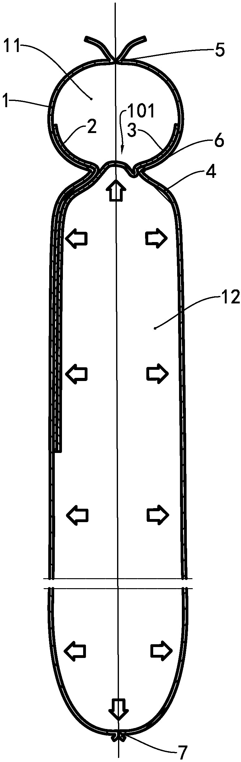
[0039] The main improvement of the present invention is on the one hand the shape of the central heat-sealing line and its positional relationship with the strip-shaped heat-resistant block, and on the other hand the inner film material. The differences between the present invention and the prior art will be described in detail below, and those skilled in the art can fully implement the embodiments of the present invention according to the contents introduced in the prior art.

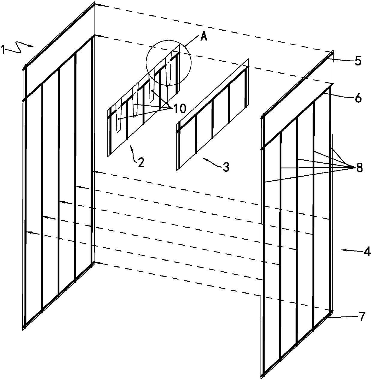
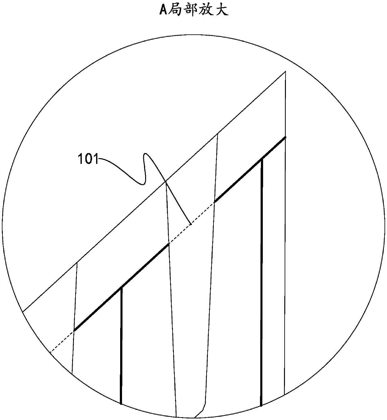
[0040] see Figure 4 , by the upper heat-sealing line 5, the middle heat-sealing line 6 and Figure 4The leftmost longitudinal side sealing line in the center forms an inflatable channel 11, and the adjacent two longitudinal heat sealing lines 8, the lower heat sealing line 7 and the middle heat sealing line 6 form an air chamber 12, and the air intake of the air chamber 12 The mouth 101 is located on the strip-shaped heat-resistant block 10, and a section of the middle heat-sealing line located in th...

no. 2 example

[0047] Only the difference between this example and the first embodiment will be described below.

[0048] The top of the heat-sealing line 6 in the middle of this example is flush with the top of the heat-resistant block 10 . The main advantage of this example is to improve the gas-holding effect of the air chamber, that is, a piece of inner film containing a nylon layer is adopted, and the air inlet of the air chamber is closed when the inner film is air-holding. In the case that the precision of the process and equipment for producing the gas sealing body is very high, this example has the advantages of straight gas-filled passages and relative saving of raw materials.

no. 3 example

[0050] The difference between this example and the first embodiment is the shape of the raised section 61, which is a quadratic arc in this example.


PUM

PropertyMeasurementUnit
Distanceaaaaaaaaaa

Abstract

The invention relates to a wrapping material with shock absorption performance, and particularly relates to an improved gas sealing member. The gas sealing member comprises two outer films and two inner films, wherein strip-shaped heat-resistant blocks are arranged at intervals on the surface, which faces the other inner film, of one inner film, and at least one inner film adopts a film containinga nylon layer. The gas sealing member has the advantage that a gas chamber is prevented from leaking.

Description

technical field [0001] This invention relates to wrapping materials having shock-absorbing properties, and in particular to gas-tight bodies made of plastic film. Background technique [0002] The gas sealing body referred to in the present invention refers to a gas sealing body composed of a plurality of air chamber cavities formed by bonding or heat welding of plastic films from a structural principle, and the gas sealing body formed after the plurality of air chamber cavities are inflated. [0003] Patent document CN1754784A discloses a fluid container, that is, the gas sealing body of the present invention. In order to form an air retention after inflating from the inflation channel to each air chamber, a stop valve is provided at the air inlet from the inflation channel to the air chamber. According to different production processes, there are different schemes for forming the air inlet. Among them, it seems that the more advanced one is to set the printing mark formed ...

Claims


Application Information

Patent Timeline
IPC IPC(8): B65D81/03
CPCB65D81/03
Inventor 谢德
Owner 珠海徐太日用品有限公司
Why Eureka
Try Eureka