
High-frequency-vibration servo hydraulic cylinder

A servo hydraulic cylinder and high-frequency vibration technology, applied in the field of hydraulic cylinders, can solve the problems of low precision, large vibration amplitude and low vibration frequency of hydraulic cylinders, and achieve the effects of good dynamic characteristics, space saving and high accuracy

Pending Publication Date: 2018-03-20
HEFEI UNIV OF TECH +2
View PDF8 Cites 6 Cited by
  • Summary
  • Abstract
  • Description
  • Claims
  • Application Information

AI Technical Summary

Problems solved by technology

[0002] The hydraulic cylinder is an actuator that converts the pressure energy of the hydraulic oil into mechanical energy to achieve linear reciprocating motion. The traditional hydraulic cylinder is generally controlled by an electro-hydraulic servo system or an electro-hydraulic proportional system. Although it can control the displacement and speed of the hydraulic system , force and other physical quantities can be accurately controlled, but direct digital control cannot be realized, and a digital / analog-analog / digital conversion device is required, which limits its application range to a certain extent. High control accuracy requirements, while the existing hydraulic cylinders are usually not high in accuracy, and there are also problems of slow system response, low vibration frequency, and large vibration amplitude

Method used


Image

  • High-frequency-vibration servo hydraulic cylinder

Examples


Embodiment Construction

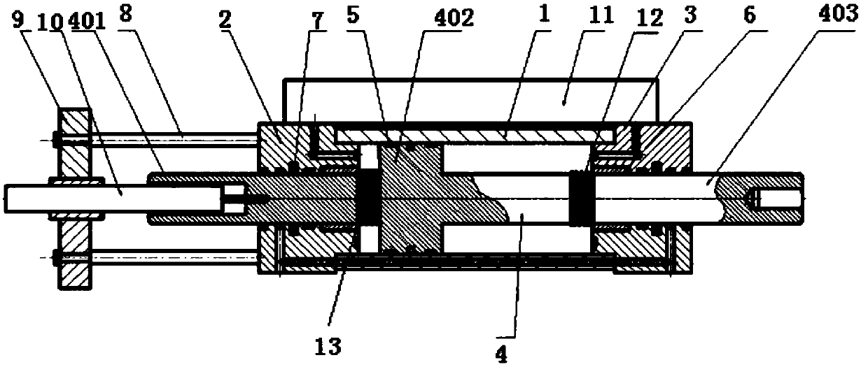
[0020] A high-frequency vibration servo hydraulic cylinder, such as figure 1 As shown, including the cylinder 1, the left and right end faces of the cylinder 1 are sealed and fixed with two identical left cylinder heads 2 and right cylinder heads 3, the cylinder 1 is sleeved with a piston rod 4, and the two ends of the piston rod 4 pass through the left and right cylinders. The cylinder head 2 and the right cylinder head 3 are sealed and fixed in the left cylinder head 2 and the right cylinder head 3;

[0021] The left cylinder head 2 and the right cylinder head 3 include a cylinder head and a sealing ring fixed on the end face of the cylinder head. The radius of the sealing ring is 3-5 cm smaller than that of the cylinder head. The outer surface of the side wall of the fixed ring, and the two end faces of the cylinder barrel 1 and the end face of the cylinder head are compressed and sealed and fixed simultaneously, and the surfaces of the left cylinder head 2 and the right cy...


PUM


Abstract

The invention discloses a high-frequency-vibration servo hydraulic cylinder. The servo hydraulic cylinder comprises a cylinder barrel; a left cylinder cover and a right cylinder cover which are identical are fixed on the left end surface and the right end surface of the cylinder barrel in a sealed manner; a piston rod is sleeved with the cylinder barrel; two ends of the piston rod penetrate through the left cylinder cover and the right cylinder cover and are fixed in the left cylinder cover and the right cylinder cover in a sealed manner; through holes are formed in the surface of the left cylinder cover and the surface of the right cylinder cover; the piston rod comprises a left piston rod, a piston and a right piston rod which are connected and fixed sequentially and are molded integrally; a piston seal is fixed on the outer surface of the side wall of the piston in a sleeving manner; the piston is in sealed connection with the inner surface of the side wall of the cylinder barrel bythe aid of the piston seal; and the outer surface of the side wall of the left piston rod and the outer surface of the side wall of the right piston rod are sleeved with metal supporting rings and piston rod seals. The hydraulic cylinder is quick in system response, good in dynamic characteristic and high in motion precision, low-amplitude and high-frequency vibration can be realized through cooperation of a servo valve group and a high-precision displacement sensor, and meanwhile, the amplitude can be adjusted as required.

Description

technical field [0001] The invention belongs to the field of hydraulic cylinders and relates to a high-frequency vibration servo hydraulic cylinder. Background technique [0002] The hydraulic cylinder is an actuator that converts the pressure energy of the hydraulic oil into mechanical energy to achieve linear reciprocating motion. The traditional hydraulic cylinder is generally controlled by an electro-hydraulic servo system or an electro-hydraulic proportional system. Although it can control the displacement and speed of the hydraulic system , force and other physical quantities can be accurately controlled, but direct digital control cannot be realized, and a digital / analog-analog / digital conversion device is required, which limits its application range to a certain extent. High control precision requirements, but the existing hydraulic cylinders usually have low precision, and there are also problems such as slow system response, low vibration frequency, and large vibra...

Claims


Application Information

Patent Timeline
IPC IPC(8): F15B15/14F15B15/28
CPCF15B15/1423F15B15/1433F15B15/1457F15B15/2815
Inventor 朱仁胜何静芳田杰刘雅萍喻航
Owner HEFEI UNIV OF TECH
Learn More