Multi-effect heater

A heater and burner technology, which is used in water heaters, fluid heaters, lighting and heating equipment, etc., can solve the problems of insufficient utilization of heat source heat, waste of heat, and limited area.

Pending Publication Date: 2018-03-20
佛山市国能宏基投资有限公司
View PDF0 Cites 2 Cited by
  • Summary
  • Abstract
  • Description
  • Claims
  • Application Information

AI Technical Summary

Problems solved by technology

Conventional oil or gas heaters are mainly composed of fans, burners, combustion chambers, and water jackets. During work, only the inner wall of the water jacket is in contact with the heat source and absorbs heat. Although many water ja

Method used


Image

  • Multi-effect heater
  • Multi-effect heater

Examples


Embodiment Construction

[0011] The present invention will be further described in detail below in conjunction with the examples, the following examples are explanations of the present invention and the present invention is not limited to the following examples.

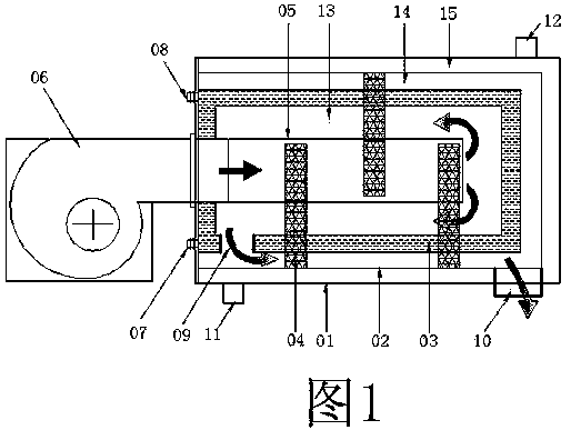
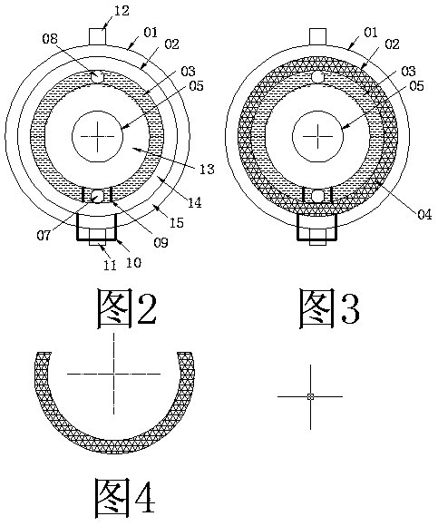
[0012] The multi-effect heater according to the present invention is mainly composed of an outer shell 01, an inner shell 02, a water jacket 03, a spoiler 04, and a combustion tube 05, which are respectively socketed and combined from outside to inside, and the flame-throwing burner 06 as a heat source is connected to the At the entrance of the combustion tube 05; set the combustion tube 05, which is slightly shorter than the inner wall length of the water jacket 03, in the middle of the water jacket 03 and reserve a space to form a circular gas chamber 13, and the length of the combustion tube 05 is shorter than the inner wall length of the water jacket 03 In order to keep the deflection distance of the gas, put the inner shell 02 on the out...


PUM

PropertyMeasurementUnit
Central angleaaaaaaaaaa

Abstract

A multi-effect heater, which is mainly composed of an outer shell, an inner shell, a water jacket, a spoiler, and a combustion tube respectively socketed from outside to inside. There is a circular heat exchange chamber between the shells, and there is a circular exhaust gas chamber between the inner shell and the outer wall of the water jacket. In the exhaust gas chamber, there are semi-circular spoilers that are relatively staggered around the water jacket. The inner wall of the water jacket and the combustion tube There is a circular gas chamber in between, the water jacket is provided with a liquid inlet, a liquid outlet and a vent, the inner shell is provided with an exhaust gas outlet and passes through the outer shell, and the outer shell is provided with a heat exchange medium inlet and a heat exchange medium outlet.

Description

technical field [0001] The invention relates to the technical field of heaters, in particular to a multi-effect heater. Background technique [0002] With the development of industry, heaters are used in various industrial heating applications, also used in the preheating of cold start of the engine, and in various space heating that require heating. [0003] At present, the commonly used heaters are mainly oil or gas heaters, because of their flexibility and stable heat source. Conventional oil or gas heaters are mainly composed of fans, burners, combustion chambers, and water jackets. During work, only the inner wall of the water jacket is in contact with the heat source and absorbs heat. Although many water jackets are equipped with heat sinks , but due to the limited area in contact with the heat source, the heat energy of the heat source is not fully utilized, and most of the heat is wasted as the high-temperature exhaust gas is discharged. Contents of the invention ...

Claims


Application Information

Patent Timeline
IPC IPC(8): F24H1/24F24H9/00
CPCF24H1/24F24H9/0005
Inventor 郎风
Owner 佛山市国能宏基投资有限公司
Why Eureka
Try Eureka