Display unit, display panel and display device

A display unit and display panel technology, applied in the directions of identification devices, optical components, electrical components, etc., can solve the problems of increasing the non-display area, unable to apply full-screen borderless flexible display products, and unavoidable fingerprint recognition, etc. The effect of experience

Active Publication Date: 2020-07-21
BOE TECH GRP CO LTD
View PDF15 Cites 0 Cited by
  • Summary
  • Abstract
  • Description
  • Claims
  • Application Information

AI Technical Summary

Problems solved by technology

In addition, flexible display fingerprint recognition requires a dedicated fingerprint recognition area, that is, a certain recessed area on the front or back is required as a fingerprint recognition area, which will not only affect the overall appearance of the product, but also increase the non-display area , cannot be applied to full-screen borderless flexible display products
However, with the increasing market demand of the current screen-to-body ratio, the area of ​​the display area continues to increase, resulting in a reduction in the frame, making it an inevitable trend to integrate fingerprint recognition technology into the display area, and there is still a lack of corresponding solutions.
[0004] Therefore, in the process of implementing the present application, the inventors found at least the following problems in the prior art: In order to realize the design of narrow frame or full screen, it is currently difficult to integrate the corresponding identification or control technology into the display area, especially for fingerprint identification For example, it is unavoidable that there is a non-display area for identifying fingerprints

Method used


Image

  • Display unit, display panel and display device
  • Display unit, display panel and display device
  • Display unit, display panel and display device

Examples


Embodiment 1

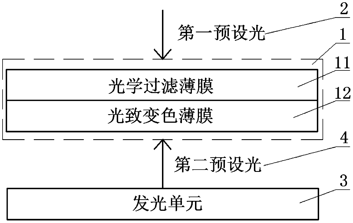
[0034] Specifically, refer to figure 1 Shown is a schematic structural diagram of an embodiment of the display unit provided by the present invention. The display unit 1 includes: a photochromic film 12 and an optical filter film 11 arranged on one side of the photochromic film 12; optionally, the photochromic film 12 is made of a reversible photochromic material, using Based on the characteristics of the reversible photochromic material, the photochromic film 12 presents a colored state under the first predetermined light 2 and a transparent state under the second predetermined light 4; the optical filter film 11 It is used to only allow the first predetermined light 2 to pass through and shine on the photochromic film 12; the other side of the photochromic film 12 is provided with a light emitting unit 3, and the light emitting unit 3 is used to emit the first Two preset light4. That is to say, by using the color-changing properties of the reversible photochromic material,...

Embodiment 2

[0042] refer to Figure 4 and Figure 5 As shown, a structure of a display panel using the above display unit is disclosed, wherein, Figure 4 A schematic structural view of an embodiment of the display panel provided by the present invention; Figure 5 A schematic structural diagram of another embodiment of the display panel provided by the present invention. Specifically, the display panel includes a flexible cover 7, a light-emitting unit 3, and a display unit 1; the flexible cover 7 is arranged on the side of the display unit 1 close to the light-emitting unit 3 and makes the photochromic The film 12 is close to the flexible cover 7; the second preset light 4 emitted by the light emitting unit 3 enters the photochromic film 12 through the flexible cover 7, and the first preset light 2 Pass through the optical filter film 11 and enter the photochromic film 12;

[0043] Alternatively, the flexible cover 7 is arranged on the side of the display unit 1 away from the light-...

Embodiment 3

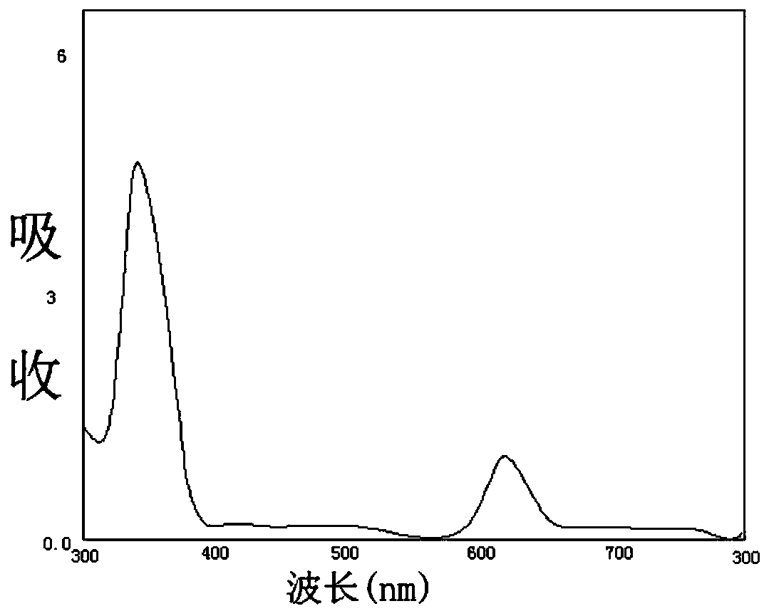
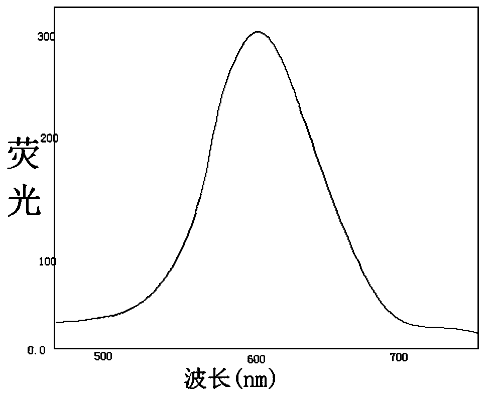
[0052] refer to Figure 8 As shown in FIG. 2 , it is a flow chart of realizing fingerprint recognition by the display device provided by the present invention. It can be seen from the figure that after the external light is incident on the flexible cover, since the optical filter film under the flexible cover has the performance of transmitting ultraviolet light and reflecting visible light, only ultraviolet light is incident on the photochromic film layer, and the photochromic film absorbs Ultraviolet light makes spirooxazine or spiropyran ring-open in photoresponse, and at the same time, polyvinylidene chloride-methyl acrylate can release hydrogen chloride to stabilize the ring-opening state of doped spirooxazine or spiropyran, so that all The above display unit exhibits stable fluorescence after being irradiated by ultraviolet light.

[0053] Optionally, the wavelength range of the ultraviolet light is 200nm-300nm, preferably 254nm; usually, the film emits fluorescence wit...


PUM


Abstract

The invention discloses a display unit, a display panel and a display device, which belong to the related technical field of displays. The display unit includes a photochromic film and an optical filter film arranged on one side of the photochromic film; the photochromic film is used to present a colored state under a first preset light, and to display a colored state under a second preset light. The bottom is in a transparent state; the optical filter film is used to allow only the first preset light to pass through and irradiate on the photochromic film; the other side of the photochromic film is provided with a light-emitting unit, and the light-emitting The unit is used to emit a second predetermined light. The present application can provide a display unit that can be integrated in the display area, which does not affect the normal display of the display area, and can display a certain area range when needed, thereby realizing corresponding identification or control functions and improving user experience.

Description

technical field [0001] The present invention relates to the technical field related to displays, in particular to a display unit, a display panel and a display device. Background technique [0002] With the development of display technology, terminal devices such as smartphones and tablet computers have become indispensable auxiliary devices in people's lives, and as these terminal devices store a large amount of personal information and other important data, their security has become increasingly difficult. especially important. At present, passwords, graphics, fingerprints and other forms are often used to realize the password protection of terminal equipment. Among them, fingerprints are composed of uneven skin lines on the surface of fingers, which are unique features of the human body, and their complexity can provide sufficient features for identification. Therefore, fingerprint recognition is to use the uniqueness and stability of fingerprints to realize identity re...

Claims


Application Information

Patent Timeline
Patent Type & Authority Patents(China)
IPC IPC(8): G09F9/00G09F9/30
CPCG09F9/00G09F9/301G02B5/23G06V40/1318H10K59/50H10K59/65H01L27/14678
Inventor 杜双蔡宝鸣卜德军刘陆陈立强
Owner BOE TECH GRP CO LTD
Why Eureka
Try Eureka