Special multifunctional tooth extraction forceps for dentistry

A multi-functional, tooth extraction forceps technology, used in dentistry, dentist forceps, applications, etc., can solve the problems of inconvenience for staff to regularly observe the symptoms of tooth recovery, inconvenience for staff to observe detailed symptoms of teeth, affecting the work efficiency of staff, etc. To achieve the effect of strong disinfection function, improve the convenience of use, and improve the cleanability

Inactive Publication Date: 2018-03-23
蒋家春
View PDF0 Cites 5 Cited by
  • Summary
  • Abstract
  • Description
  • Claims
  • Application Information

AI Technical Summary

Problems solved by technology

[0003] In the prior art, the existing tooth extraction forceps do not have lighting. During the use of the tooth extraction forceps, it is inconvenient for the staff to observe the detailed symptoms inside the teeth, which affects the work efficiency of the staff. The existing tooth extraction forceps have no camera function. The tooth extraction work is not comprehensive enough, it is inconvenient for the staff to regularly observe the symptoms of tooth recovery, and the tooth extraction forceps need to be cleaned and disinfected after use, which increases the labor intensity of the staff. The existing tooth extraction forceps have single functions, so there is an urgent need for a multifunctional dental special Tooth extraction forceps to solve the above problems

Method used


Image

  • Special multifunctional tooth extraction forceps for dentistry
  • Special multifunctional tooth extraction forceps for dentistry
  • Special multifunctional tooth extraction forceps for dentistry

Examples


specific Embodiment approach

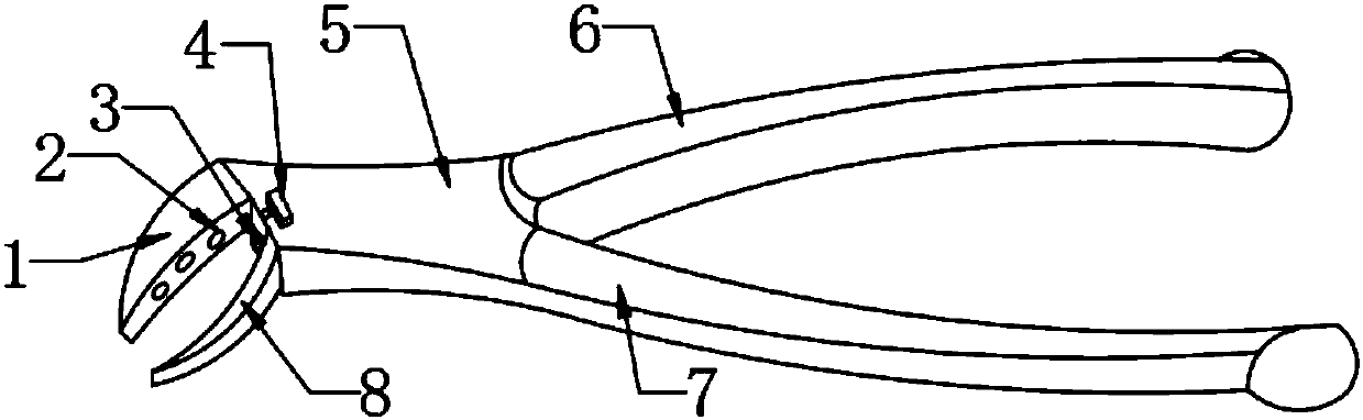
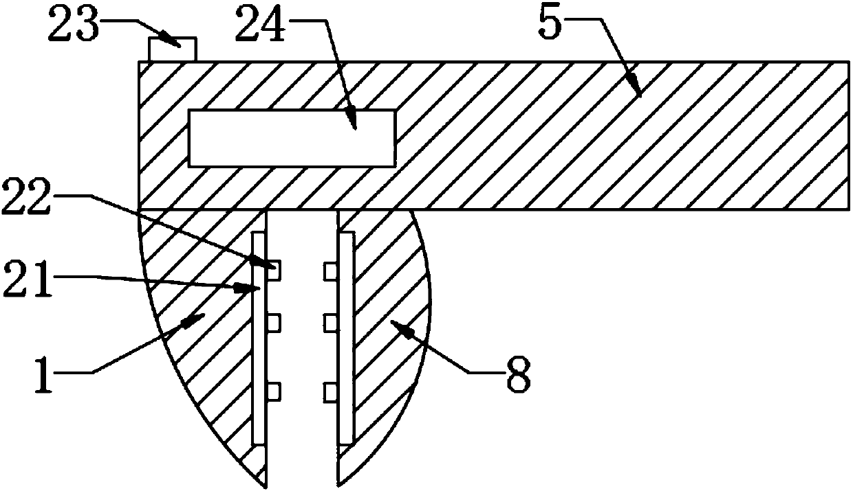
[0027] Specific embodiments: before using the main body 5 of the device to extract teeth, the staff first turns on the lighting button 23, the lighting button 23 is switched to the on state, the storage battery 24 transmits the electric energy to the LED lamp 22 through the wire, and the LED lamp 22 converts the electric energy For light energy, the LED lamp 22 emits light to realize the effect of lighting. This design can improve the light intensity for the staff, make the staff's field of vision wider, and solve the problem that the lighting function of the original tooth extraction forceps is not comprehensive enough.

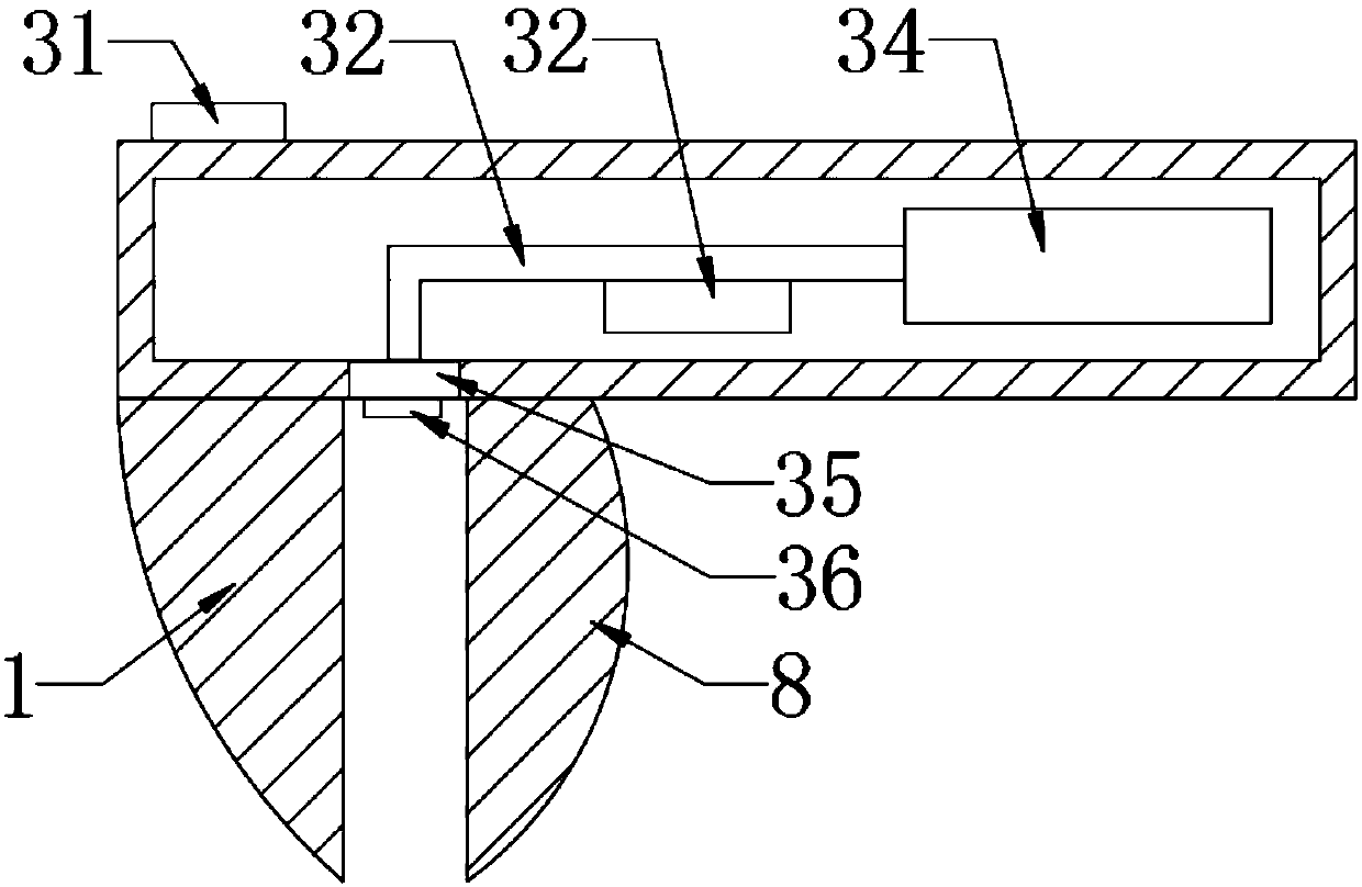
[0028] When the staff is carrying out tooth extraction work, the staff presses the telescopic button 35, and the telescopic button 35 is switched to the on state, and the storage battery 24 transmits electric energy to the electric telescopic rod 44, and the electric telescopic rod 44 starts to stretch out after receiving the electric energy. The telescopic r...


PUM


Abstract

The invention provides a multi-functional tooth extraction forceps for dentistry, which includes a main body of the device, a light slot, an LED light, a micro pump, an alcohol storage box, a camera, and an electric telescopic rod. On both sides, LED lights are assembled inside the light groove. This design solves the problem that the lighting function of the original tooth extraction forceps is not comprehensive enough. The micropump is installed on the lower end of the water pipe, and the alcohol storage box is installed on the right side of the main body of the device. The wires passing through the micropump It is connected with the disinfection button. This design solves the problem that the original tooth extraction forceps has no disinfection function. The camera is fixed on the left end of the connecting rod through bolts. The electric telescopic rod is connected to the camera through the connecting rod. The electric telescopic rod is assembled inside the protective cover. This design solves the problem that the original tooth extraction forceps has no camera function, and the invention is convenient to use, has strong disinfection function, strong functionality and wide applicability.

Description

technical field [0001] The invention is a special multifunctional tooth extraction forceps for dentistry, which belongs to the technical field of medical equipment. Background technique [0002] Tooth extraction forceps are pliers used to extract teeth during tooth extraction. Consists of pliers handle, joint and pliers beak. Tooth extraction forceps are divided into adult tooth extraction forceps and children tooth extraction forceps, and the gill structure of the tooth extraction forceps has a penetrating gill structure and a stacked gill structure. [0003] In the prior art, the existing tooth extraction forceps do not have lighting. During the use of the tooth extraction forceps, it is inconvenient for the staff to observe the detailed symptoms inside the teeth, which affects the work efficiency of the staff. The existing tooth extraction forceps have no camera function. The tooth extraction work is not comprehensive enough, it is inconvenient for the staff to regularl...

Claims


Application Information

Patent Timeline
Patent Type & Authority Applications(China)
IPC IPC(8): A61C3/14A61C19/00A61B1/24A61B1/04A61B1/06A61L2/18A61L101/34
CPCA61C3/14A61B1/04A61B1/0684A61B1/24A61C19/00A61L2/18A61L2202/24
Inventor 蒋家春
Owner 蒋家春
Why Eureka
Try Eureka