Automatic plate production device

An automatic production and plate technology, applied in unloading devices, devices for coating liquid on the surface, transportation and packaging, etc., can solve the problems of low application efficiency, easy spillage of coatings, and easy damage of coatings, etc., to achieve improved Efficiency, avoiding waste, high efficiency effect

Active Publication Date: 2018-03-23
爱耐福(山东)新材料科技有限公司
View PDF5 Cites 24 Cited by
  • Summary
  • Abstract
  • Description
  • Claims
  • Application Information

AI Technical Summary

Problems solved by technology

[0005] One of the purposes of the present invention is to address the deficiencies in the prior art, by opening an opening of the same size as the board that needs coating on the feed box, and by squeezing the material in the feed box during the process of pushing the board to move on the opening Paint is used to apply paint to the lower surface of the board to overcome the troublesome operation when applying paint to the board, the paint is easy to scatter and cause waste, the application efficiency is low, and the problem of easy damage during the coating transfer process

Method used


Image

  • Automatic plate production device
  • Automatic plate production device
  • Automatic plate production device

Examples


Embodiment 1

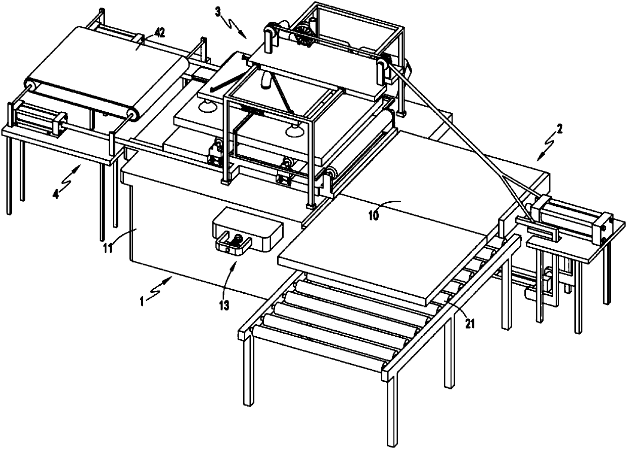
[0045] Such as figure 1 , figure 2 , image 3 , Figure 4 , Figure 5 , Image 6 , Figure 7 , Figure 8 , Figure 9 with Figure 10 As shown, a kind of plate automatic production device comprises coating device 1, and described coating device 1 comprises material box 11, is arranged in the material box 11 and is used for extruding the coating material in material box 11 to make coating contact the lower surface of plate material 10 The extrusion mechanism 12 and the overflow mechanism 13 arranged on the side of the material box 11, the upper surface of the material box 11 is provided with an opening 14, and the opening 14 is provided with a cover plate 15;

[0046] The feeding device 2, the feeding device 2 is arranged at the front end of the material box 11, the feeding device 2 includes a feeding roller set 21 and a pushing mechanism 22, and the pushing mechanism 22 is used to push the plate 10 along the upper end of the opening 14 Push the cover plate 15 away fro...

Embodiment approach

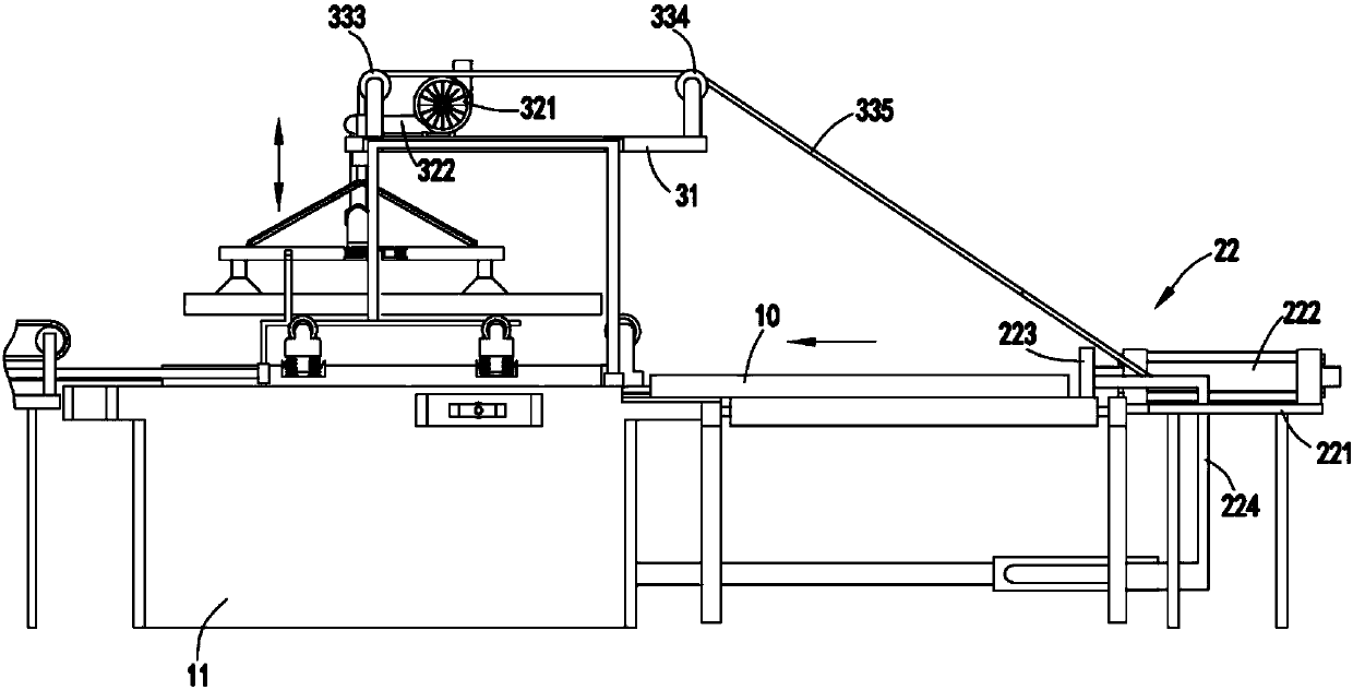
[0054] Further, as image 3 with Figure 4 As shown, as yet another preferred embodiment, the suction mechanism 32 includes a suction machine 321 and a hose 322 whose end communicates with the suction port of the suction machine 321;

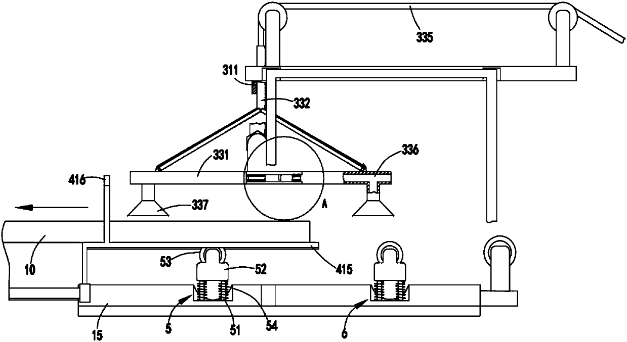
[0055] The suction mechanism 33 includes a suction disc 331, a guide rod 332 fixedly connected at one end to the center of the suction disc 331, a first pulley 333 and a second pulley 334 arranged on the bracket 31, and a first pulley 333 and a second Pulley 334 and the traction rope 335 that one end is fixedly connected with the other end of guide bar 332, and the other end of described traction rope 335 is fixedly connected with connecting frame 224;

[0056] A cavity 336 is provided inside the suction plate 331, and the other end of the flexible tube 322 is fixedly connected to the suction plate 331 and communicated with the cavity 336. There are a number of cavities connected to the four corners of the bottom surface of the suction plate 33...

Embodiment 2

[0067] Such as figure 1 , figure 2 , image 3 , Figure 4 , Figure 5 , Image 6 , Figure 7 , Figure 8 , Figure 9 with Figure 10 As shown, the components that are the same as or corresponding to those in the first embodiment are marked with the corresponding reference numerals in the first embodiment. For the sake of simplicity, only the differences from the first embodiment will be described below. The difference between the second embodiment and the first embodiment is: further, the overflow mechanism 13 includes an overflow box 131, an overflow block 132 that slides with the inner wall of the overflow box 131, and is arranged on the overflow The support member 133 on one side of the box body 131 and the guide rod 136 that slides with the guide hole a134 provided on the side of the overflow tank body 131 and the guide hole b135 provided on the support member 133, one end of the guide rod 136 and The overflow block 132 is fixedly connected, the guide rod 136 is ...


PUM


Abstract

The invention relates to an automatic plate production device which comprises a coating device, a feeding device, an absorption device and an output device. The coating device comprises a coating box,a squeezing mechanism and an overflowing mechanism, wherein the squeezing mechanism is arranged in the coating box and squeezes the coating in the coating box, and the overflowing mechanism is arranged on the side edge of the coating box; and the coating box is provided with an opening, and the opening is provided with a cover plate. The feeding device is arranged at the front end of the coatingbox and comprises a feeding roller set and a push mechanism, wherein the push mechanism pushes a plate to move along the upper end of the opening and meanwhile pushes the plate to move away. The absorption device is arranged on the coating box and comprises a bracket, a suction mechanism and an absorption mechanism, wherein the suction mechanism and the absorption mechanism are installed on the bracket; and the absorption mechanism absorbs the coated plate and drives the plate to move upwards. The output mechanism is arranged at the rear end of the coating box and comprises a push-pull mechanism and a conveyer belt, and the push-pull mechanism pushes the cover plate to cover the opening and drives the plate to the conveyer belt to be output in the reset process. By means of the automatic plate production device, the problems that the operation of plate coating is troublesome, the coating is prone to falling, waste is caused, coating efficiency is low, and a coating layer is prone to bedamaged are solved.

Description

technical field [0001] The invention relates to the technical field of coating equipment, in particular to an automatic plate production device. Background technique [0002] Generally, air purifiers, paints or waterproof materials are evenly sprayed on ceramic tiles, glass or metal plates, etc. by hand. This method is prone to uneven application, and it is also easy to cause the inner surfaces of ceramic tiles, glass or metal plates to be smeared If the materials are applied, the ceramic tiles, glass or metal plates can no longer be used. In addition, mechanical smearing tools are used. The disadvantages are: the operation is complicated, and the problem that the inner surfaces of ceramic tiles, glass or metal plates are also smeared cannot be solved. Does not hold materials such as tile, glass or sheet metal well. [0003] A Chinese invention patent with the application number CN201510405100.7 discloses a spraying system that evenly distributes the paint on the surface of...

Claims


Application Information

Patent Timeline
Patent Type & Authority Applications(China)
IPC IPC(8): B05C5/02B05C11/10B05C13/02B65G47/91B65G49/06B65G49/08
CPCB05C5/02B05C11/1039B05C13/02B65G47/912B65G49/061B65G49/08B65G2201/022
Inventor 张飞张颍龙张文
Owner 爱耐福(山东)新材料科技有限公司
Why Eureka
Try Eureka