Center frame for machining strip-shaped workpieces

A strip workpiece and center frame technology, which is applied to metal processing machinery parts, metal processing equipment, manufacturing tools, etc., can solve the problems of unable to keep the supporting claws stably fitted, the workpiece and the supporting claws are worn, and additional operations are added. Improve adjustment accuracy and service life, reduce wear and bumps, reduce the effect of additional operations

Inactive Publication Date: 2018-03-23
弘毅天承知识产权股份有限公司
View PDF0 Cites 0 Cited by
  • Summary
  • Abstract
  • Description
  • Claims
  • Application Information

AI Technical Summary

Problems solved by technology

The steady frame used in the pipe processing lathe of the prior art when processing the tubular workpiece adopts the way of adding lubricating oil to keep the supporting claws in good contact with the workpiece, which not only increases additional operations, but is easily ignored, resulting in the The supporting claws are prone to wear and hinder the rotation of the workpiece, affecting the machining accuracy and reducing the machining efficiency
And only using three supporting claws to clamp the workpiece cannot keep the supporting claws and the workpiece in a stable fit, which may cause the workpiece to fall off during processing

Method used


Image

  • Center frame for machining strip-shaped workpieces

Examples


Embodiment 1

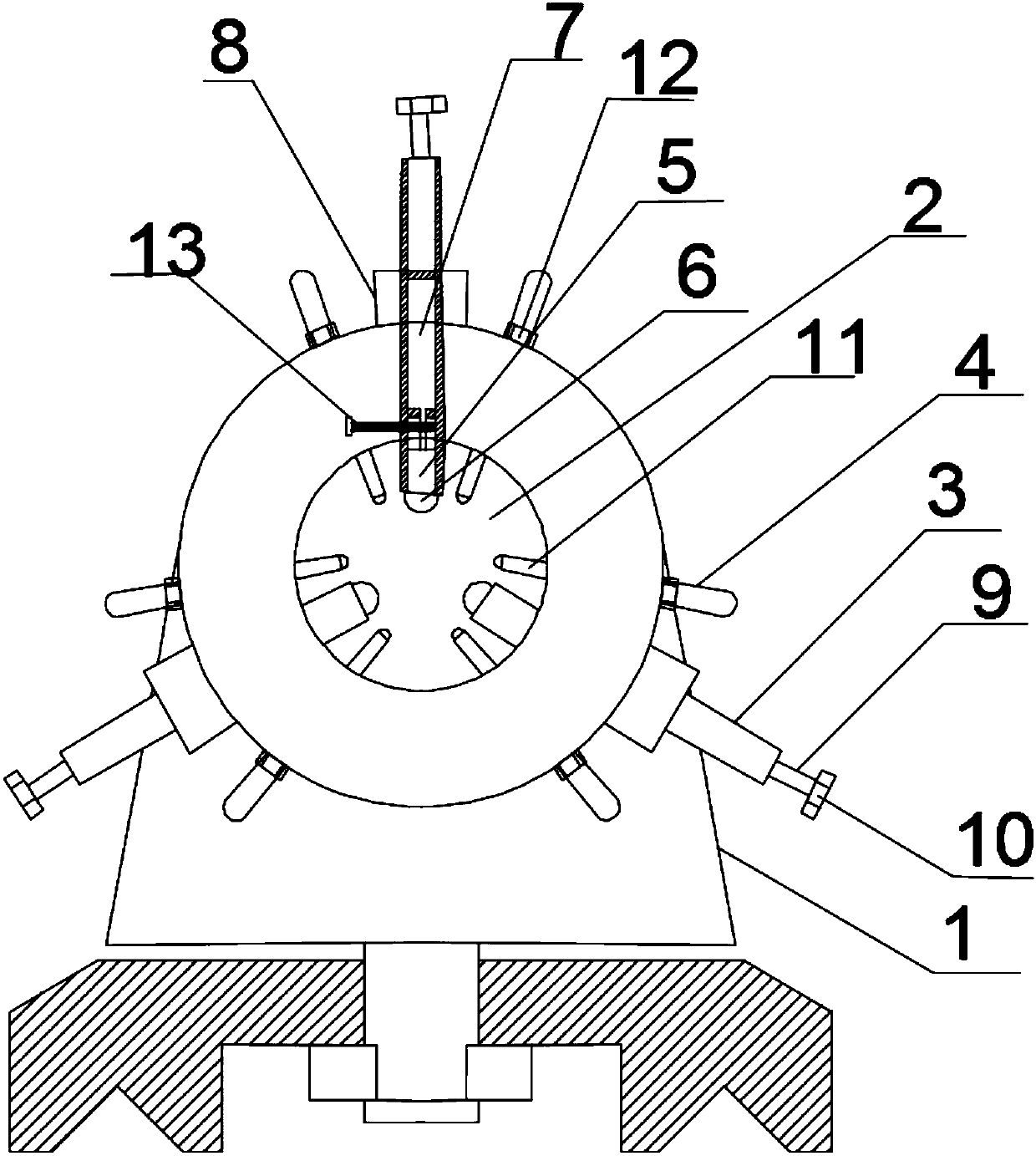
[0021] Such as figure 1 As shown, the present invention provides a center frame for processing strip-shaped workpieces, including a center frame body 1, a cavity portion 2 is arranged on the center frame body 1, the cavity portion is a hollow structure, and the center frame body 1 also includes three compression mechanisms 3 and six adjustment mechanisms 4, the three compression mechanisms 3 are uniformly arranged on the peripheral side of the cavity part 2, and the three compression mechanisms 3 and six adjustment mechanisms 4 One end of one end extends in the hollow structure of cavity part 2, and this end is provided with blind hole 5, and described blind hole 5 is provided with ball 6 or pulley, and the other of three pressing mechanisms 3 and six adjusting mechanisms 4 One end is provided with threads and is connected with the cavity part 2 through threads.

Embodiment 2

[0023] Such as figure 1 As shown, the present invention provides a center frame for processing strip-shaped workpieces, including a center frame body 1, a cavity portion 2 is arranged on the center frame body 1, the cavity portion is a hollow structure, and the center frame body 1 also includes three compression mechanisms 3 and six adjustment mechanisms 4, the three compression mechanisms 3 are uniformly arranged on the peripheral side of the cavity part 2, and the three compression mechanisms 3 and six adjustment mechanisms 4 One end of one end extends in the hollow structure of cavity part 2, and this end is provided with blind hole 5, and described blind hole 5 is provided with ball 6 or pulley, and the other of three pressing mechanisms 3 and six adjusting mechanisms 4 One end is provided with threads and is connected with the cavity part 2 through threads.

[0024] A lubricating oil chamber 7 is disposed inside the pressing mechanism 3 disposed directly above the cavity...

Embodiment 3

[0026] Such as figure 1 As shown, the present invention provides a center frame for processing strip-shaped workpieces, including a center frame body 1, a cavity portion 2 is arranged on the center frame body 1, the cavity portion is a hollow structure, and the center frame body 1 also includes three compression mechanisms 3 and six adjustment mechanisms 4, the three compression mechanisms 3 are uniformly arranged on the peripheral side of the cavity part 2, and the three compression mechanisms 3 and six adjustment mechanisms 4 One end of one end extends in the hollow structure of cavity part 2, and this end is provided with blind hole 5, and described blind hole 5 is provided with ball 6 or pulley, and the other of three pressing mechanisms 3 and six adjusting mechanisms 4 One end is provided with threads and is connected with the cavity part 2 through threads.

[0027] A lubricating oil chamber 7 is disposed inside the pressing mechanism 3 disposed directly above the cavity...


PUM


Abstract

The invention discloses a center frame for processing strip-shaped workpieces, relates to the field of lathe accessory equipment, solves the problem that the existing center frame adopts the method of adding lubricating oil to maintain good contact between supporting claws and workpieces, and only uses three supporting claw clips Holding the workpiece, there is a problem that the support claw cannot be kept in a stable fit with the workpiece, causing the workpiece to fall off during processing. It includes a center frame body, on which a cavity with a hollow structure is set, and the center frame body also includes three pressing mechanisms and six adjustment mechanisms, and the three pressing mechanisms are evenly spaced around the cavity , three pressing mechanisms and six adjusting mechanisms extending to one end of the hollow structure inside the cavity are provided with blind holes, balls or pulleys are arranged in the blind holes, and the other ends of the three pressing mechanisms and six adjusting mechanisms One end is provided with threads and is connected with the cavity part through threads. The invention has the advantages of simple structure, stable contact between the supporting claw and the workpiece, and small friction, and is suitable for turning the elongated shaft.

Description

technical field [0001] The invention relates to the technical field of lathe accessory equipment, and more specifically relates to a center frame for processing strip-shaped workpieces. Background technique [0002] The center frame refers to the auxiliary device used to radially support the rotating workpiece during the machining process, and there is no relative axial movement with the workpiece during processing. The center frame is directly supported in the middle of the workpiece. When the workpiece can be turned in sections, the center frame is supported in the middle of the workpiece. In this way, the L / d value is reduced by half, and the rigidity of the slender shaft can be increased several times. Before the workpiece is mounted on the center frame, a groove supporting the center frame supporting claw must be turned in the middle of the blank. The surface roughness and cylindricity error should be small, otherwise the accuracy of the workpiece will be affected. Whe...

Claims


Application Information

Patent Timeline
Patent Type & Authority Applications(China)
IPC IPC(8): B23Q1/76
CPCB23Q1/76
Inventor 赵红昌曹月琴章显红
Owner 弘毅天承知识产权股份有限公司
Why Eureka
Try Eureka