Optical trap system for point source transmittance test

A point source transmittance and optical trap technology, applied in the field of optical trap systems, can solve the problems of high cost and difficult engineering implementation, and achieve the effects of low cost, low engineering implementation difficulty and compact structure

Active Publication Date: 2018-03-23
CHANGCHUN INST OF OPTICS FINE MECHANICS & PHYSICS CHINESE ACAD OF SCI
View PDF4 Cites 0 Cited by
  • Summary
  • Abstract
  • Description
  • Claims
  • Application Information

AI Technical Summary

Problems solved by technology

However, the existing optical trap system is difficult to meet the dual requirements of stray light suppression ability and compact structure
For example, when the foreign DCC optical trap system is applied to the high-precision point source transmittance test of a large space telescope with an outer envelope size of 8.5m×2.7m×3.8m, the test area is about 30m×20m=600m 2 , so that the project implementation is difficult and costly

Method used


Image

  • Optical trap system for point source transmittance test
  • Optical trap system for point source transmittance test
  • Optical trap system for point source transmittance test

Examples


Embodiment Construction

[0027] In order to enable those skilled in the art to better understand the solutions of the present invention, the following will clearly and completely describe the technical solutions in the embodiments of the present invention in conjunction with the drawings in the embodiments of the present invention. Obviously, the described embodiments are only It is an embodiment of a part of the present invention, but not all embodiments. Based on the embodiments of the present invention, all other embodiments obtained by persons of ordinary skill in the art without making creative efforts shall fall within the protection scope of the present invention.

[0028] The terms "first", "second", "third", "fourth", etc. (if any) in the description and claims of the present invention and the above drawings are used to distinguish similar objects and not necessarily Describe a specific order or sequence. It is to be understood that the terms so used are interchangeable under appropriate cir...


PUM

PropertyMeasurementUnit
surface roughnessaaaaaaaaaa

Abstract

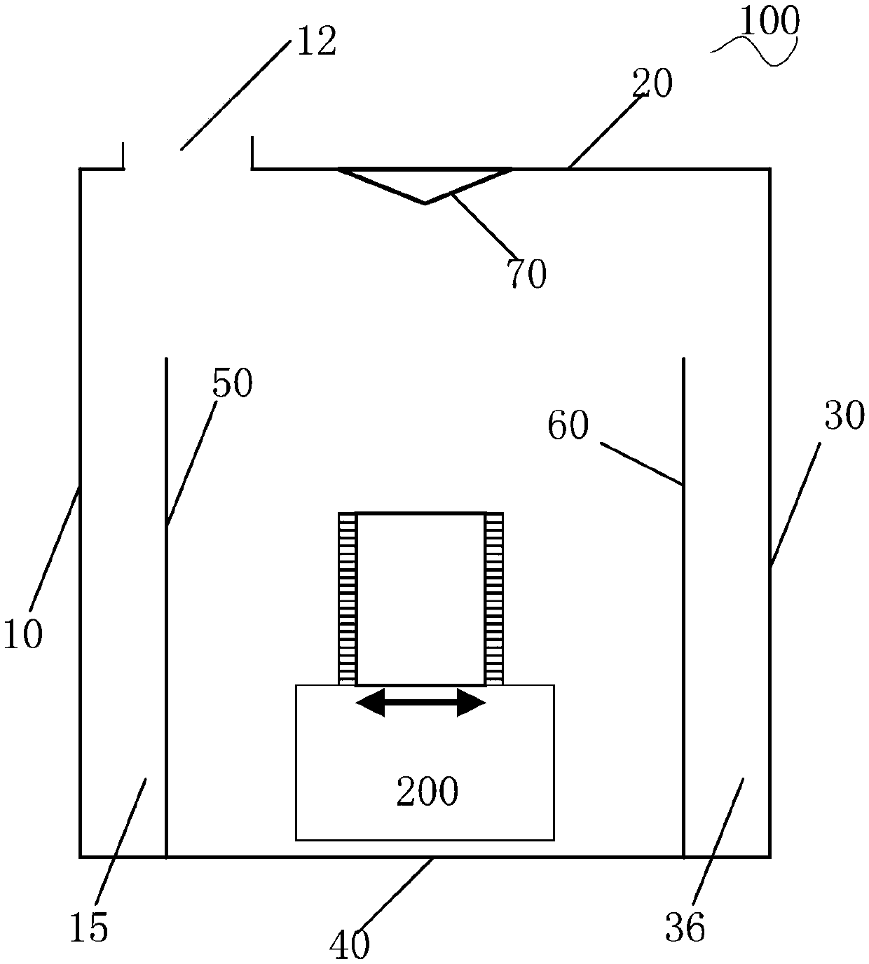
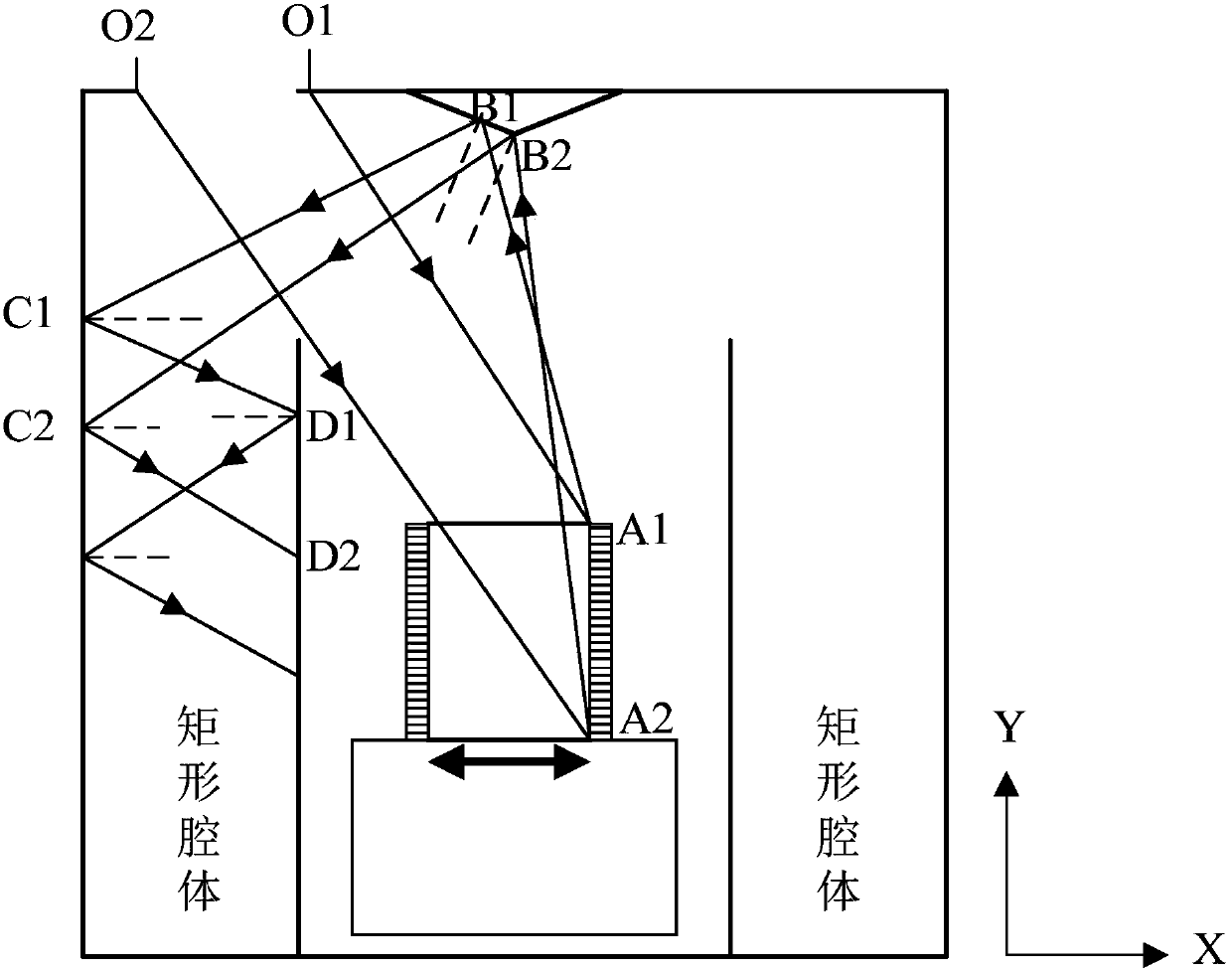
The embodiment of the invention discloses an optical trap system for point source transmittance test. The optical trap system adopts four scattering surfaces to form a test environment, and two scattering surfaces are arranged on the side of the test environment to form a cavity. A predetermined scattering surface is provided with a light opening, and the bottom edge of an isosceles triangle prismscattering surface is closely attached to the predetermined scattering surface, so that the scattering surfaces cover the object-side field of view of a system to be tested. According to the opticaltrap system provided by the embodiment of the invention, stray light in the background environment returns to the imaging field of view of the system to be tested after at least six internal wall reflections; the system has a good stray light suppression effect, so that the test accuracy is up to 10 to 10 levels; the optical trap system has the advantages of compact structure, easy engineering realization and low cost.

Description

technical field [0001] The invention relates to the technical field of space optics, in particular to an optical trap system used for high-precision point source transmittance testing of large space telescopes. Background technique [0002] With the development of aerospace technology, the manned space station project has become a major opportunity for space science, application and technology to achieve leapfrog development. In the process of deepening the demonstration of space station applications, it is necessary to complete observation tasks such as multi-band imaging of large sky areas with high angular resolution and seamless spectral depth survey functions. At present, space telescopes with high dynamic and high-performance detection capabilities of stars above AB26 are used to realize the above-mentioned observation tasks. The stray light suppression capability of the optical system of the space telescope is usually measured by the point source transmittance (PST) ...

Claims


Application Information

Patent Timeline
Patent Type & Authority Applications(China)
IPC IPC(8): G01M11/02G01N21/59G02B17/02
Inventor 曹智睿董吉洪
Owner CHANGCHUN INST OF OPTICS FINE MECHANICS & PHYSICS CHINESE ACAD OF SCI
Why Eureka
Try Eureka