Vertical tensile test device containing novel fibre cloth clamp

A tensile test, fiber cloth technology, used in measuring devices, using stable tension/pressure to test material strength, instruments, etc., can solve problems such as uneven force transmission of fiber cloth fixtures, and achieve data accuracy, guarantee Stability, the effect of improving usage

Pending Publication Date: 2018-03-23
DALIAN UNIV OF TECH
View PDF0 Cites 3 Cited by
  • Summary
  • Abstract
  • Description
  • Claims
  • Application Information

AI Technical Summary

Problems solved by technology

[0005] The technical problem to be solved by the present invention is to overcome the defect that most of the existing single shear test devices are laterally loaded and the force transmission of the fiber cloth clamp is uneven, and to provide a vertical tensile test device containing a new type of fiber cloth clamp. The hinges are directly connected, and can ensure that the fiber cloth is evenly stressed at the end, so as to obtain accurate and stable test data, and simplify the centering process before the test

Method used


Image

  • Vertical tensile test device containing novel fibre cloth clamp
  • Vertical tensile test device containing novel fibre cloth clamp
  • Vertical tensile test device containing novel fibre cloth clamp

Examples


Embodiment 1

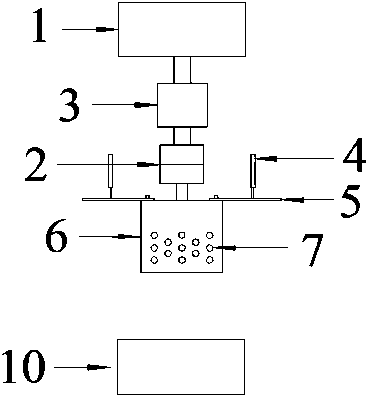
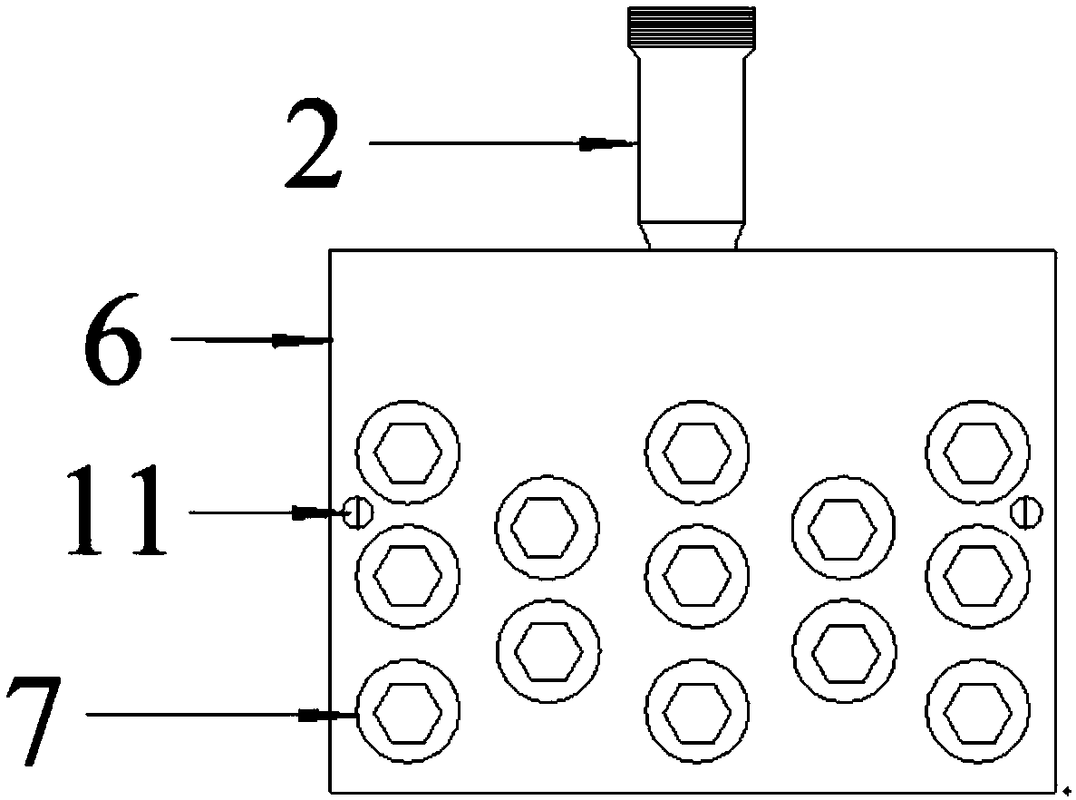
[0034] Image 6 It is a schematic diagram of the vertical tensile test device containing the novel fiber cloth clamp applied to the unidirectional tensile test of the fiber cloth, which is to directly insert the upper part of the FRP sheet 13 into the steel splint 12 with sawtooth 8, and then use The small bolts 11 are pre-tightened, and 13 high-strength bolts 7 are fastened in turn at the same time to ensure that the final force of the FRP sheet 13 is uniform, and the lower part of the FRP sheet 13 is directly placed in the fixture 9 of the testing machine and tightened. During the test, the lower chuck 10 of the testing machine remains stationary, and the upper chuck 1 of the testing machine moves upward continuously according to the displacement loading mode. The load sensor 3 located on the upper part of the ball joint 2 is used to record the real-time change of the load, and is installed on the main body of the fixture. Two displacement gauges (LVDT) 4 on the steel sheet ...

Embodiment 2

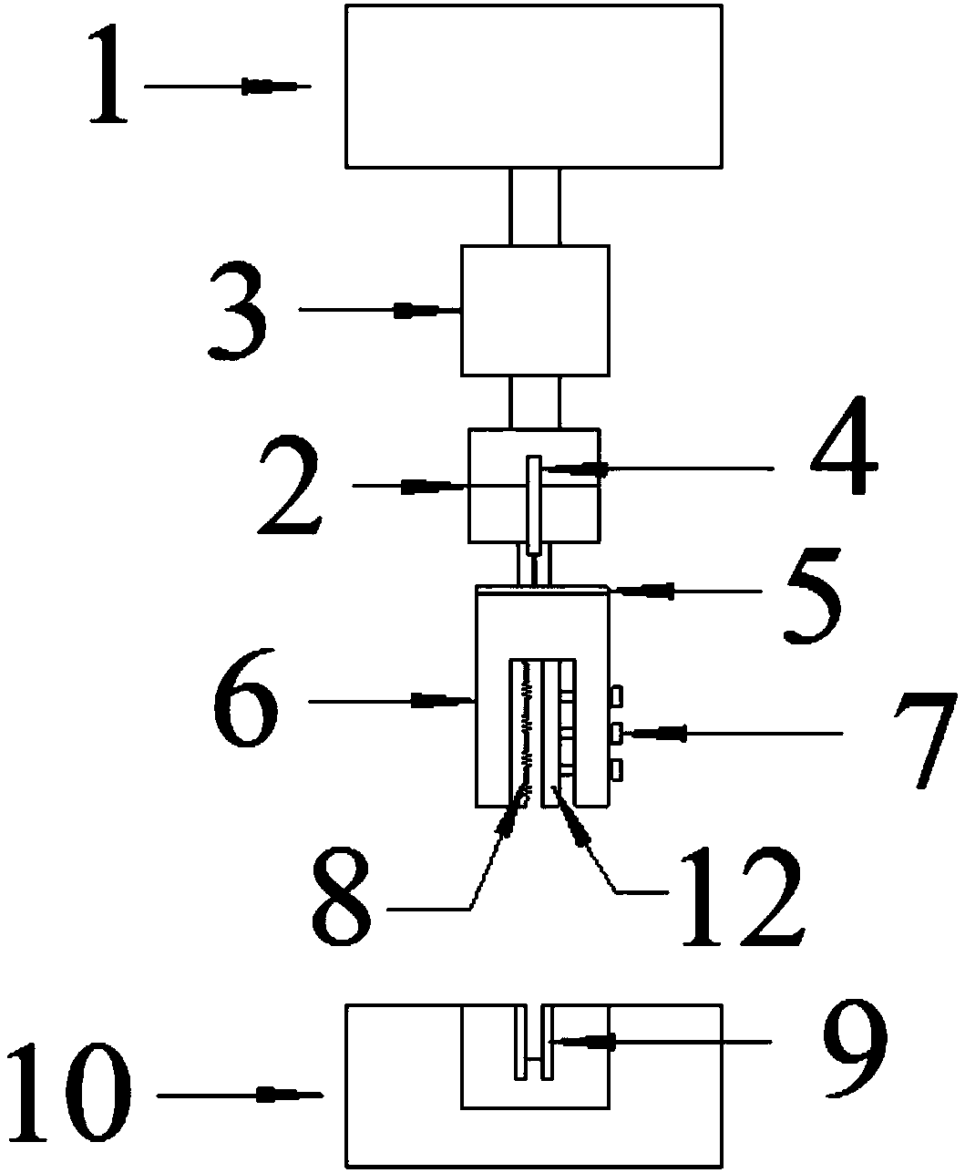
[0036] Figure 7It is a schematic diagram of the single-sided shear test of the vertical tensile test device containing the new fiber cloth clamp applied to the FRP-concrete interface. The upper pressing plate 14, the fixing screw 16 and the bottom plate 19 for fixing the concrete are first combined into a frame and then passed through The lower chuck 10 of the testing machine is directly fixed, and then the FRP sheet 13 is pasted on the surface of the concrete specimen 17 with epoxy resin glue in advance, and then placed on the bottom plate 19 as a whole, and the concrete upper plate 14 is fixed and the concrete side is fixed. The plate 15 is fixed, and then the concrete front screw 18 is locked and fixed to ensure that the lower end of the concrete specimen 17 does not have a large displacement outside the loading surface, and the upper part of the FRP sheet 13 is directly inserted into the steel splint 12 with sawtooth 8 Then use small bolts 11 for pre-tightening, and at th...


PUM


Abstract

The invention belongs to the technical field of tensile testing devices, and in particular relates to a vertical tensile testing device containing a novel fiber cloth clamp. A vertical tensile test device containing a new type of fiber cloth fixture, including fiber cloth fixture, testing machine chuck, load sensor and displacement meter; fiber cloth fixture includes fixture main body steel shell, high strength bolts, small bolts, spherical hinge and The splint, the chuck of the testing machine includes the upper chuck of the testing machine and the lower chuck of the testing machine; the inner clamp of the testing machine is fixed in the center of the lower chuck of the testing machine, and is placed under the steel shell of the main body of the clamp as a whole, and is used for other small test devices or fiber Fixing of the cloth. The invention overcomes the defects that most of the existing single shear test devices are laterally loaded and the force transmission of the fiber cloth clamp is uneven, and can ensure that the force of the fiber cloth at the end is uniform, so as to obtain accurate and stable test data.

Description

technical field [0001] The invention belongs to the technical field of tensile testing devices, and in particular relates to a vertical tensile testing device containing a novel fiber cloth clamp. Background technique [0002] Usually, before systematically analyzing the bonding performance of the FRP-concrete interface, the relevant basic mechanical performance indicators of the fiber cloth must be obtained, such as ultimate tensile strength, elastic modulus, Poisson's ratio, elongation and other parameters, Therefore, it is necessary to first make the fiber cloth into a standard test specimen according to the specific size requirements in the "Test Method for Tensile Properties of Oriented Fiber Reinforced Plastics", and then paste local reinforcement sheets (generally aluminum alloy plates or fiber Reinforced plastic plate) and then conduct a unidirectional tensile test, that is, place the reinforcing sheet on the fixture of the testing machine for axial tension. [0003...

Claims


Application Information

Patent Timeline
Patent Type & Authority Applications(China)
IPC IPC(8): G01N3/04G01N3/08
CPCG01N3/04G01N3/08G01N2203/0282
Inventor 王吉忠杨俊龙
Owner DALIAN UNIV OF TECH
Why Eureka
Try Eureka