
Automatically rotary-type adjustable transformer

A transformer and spin-type technology, applied in the field of transformers, can solve the problems of voltage output voltage deviating from the preset voltage, the inconvenient realization of transformers, and restrictions on the popularization and application of adjustable transformers, so as to avoid over-rotation, improve accuracy, The effect of improving the adjustment accuracy

Inactive Publication Date: 2018-03-23
魏海峰
View PDF9 Cites 0 Cited by
  • Summary
  • Abstract
  • Description
  • Claims
  • Application Information

AI Technical Summary

Problems solved by technology

[0002] In low-voltage and ultra-low-voltage power transmission and transformation, transformers are irreplaceable devices. Although there are many types of existing transformers, most of them are designed as specific transformer structures. For some special fields, it is often necessary to adjust and transform the transformer , the general transformer cannot be realized conveniently. The motor is used to control the rotation of the rotor shaft to change the relative electrical angle of the stator and the rotor. The stator is the primary winding of the transformer, and the rotor is the secondary winding of the transformer, so as to continuously change the voltage. Output size, realize the ratio adjustment of input and output voltage
[0003] The disadvantage of the prior art structure is that the motor drives the rotor shaft to rotate inside the transformer, but the rotation of the motor has the effect of inertia. When the output voltage of the transformer reaches a preset value, the motor will continue to rotate under the effect of inertia. Rotation causes the output voltage of the transformer to deviate from the preset voltage, which means that the transformation ratio of the adjustable transformer cannot be accurately controlled, which limits the popularization and application of the adjustable transformer in the field of high-voltage technology

Method used


Image

  • Automatically rotary-type adjustable transformer
  • Automatically rotary-type adjustable transformer
  • Automatically rotary-type adjustable transformer

Examples


Embodiment Construction

[0040] The present invention will be further described in detail below in conjunction with the accompanying drawings, so that those skilled in the art can implement it with reference to the description.

[0041] It should be understood that terms such as "having", "comprising" and "including" as used herein do not entail the presence or addition of one or more other elements or combinations thereof.

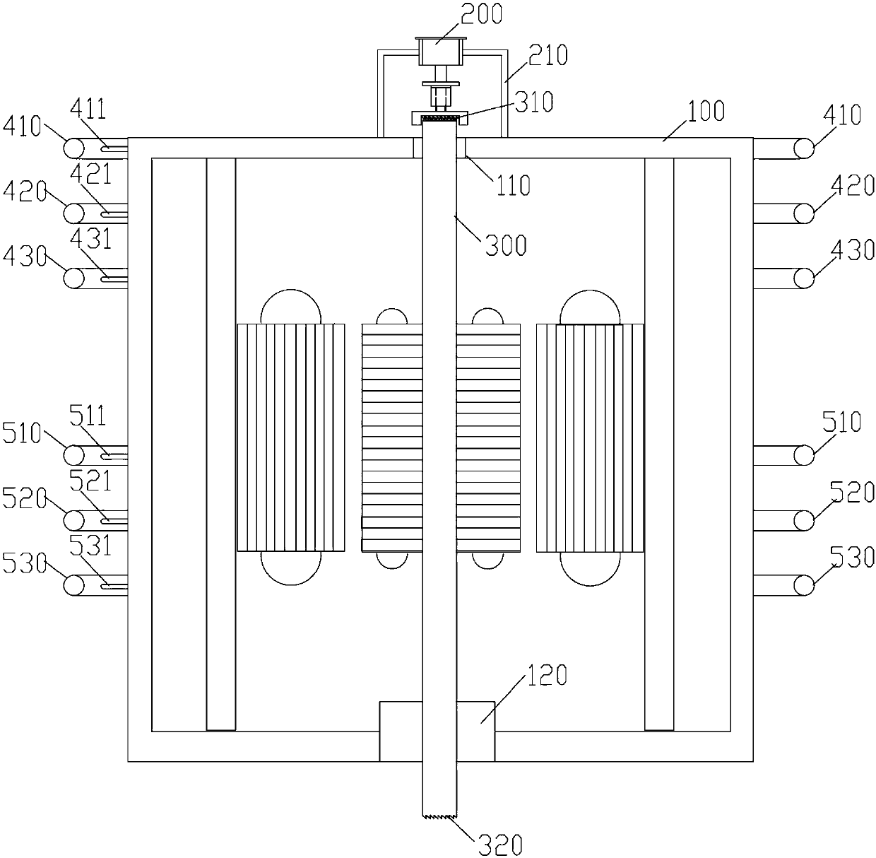
[0042] The invention provides a spin adjustable transformer, such as Figure 1-9 As shown, a rotor shaft 300 is rotated inside the transformer body 100. A rotor winding is wound on the rotor shaft 300. A stator winding is arranged on the transformer body 100 on the outer periphery of the rotor winding. The rotor winding is the secondary winding of the transformer. The stator winding is the primary winding of the transformer. The output voltage of the transformer is changed by changing the electrical angle between the rotor winding and the stator winding. The rotor shaft 300 is dr...


PUM


Abstract

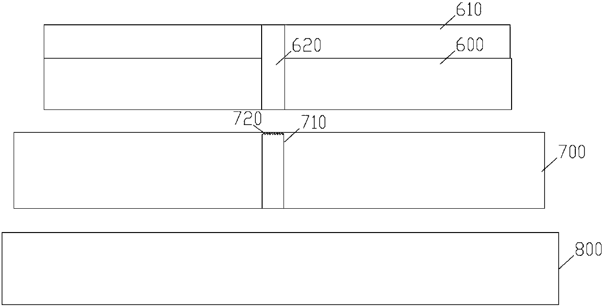
The invention discloses an automatically rotary-type adjustable transformer. The transformer includes a transformer body, a pressing mechanism, a voltage collector, a first high-voltage conductive ring, a second high-voltage conductive ring, a third high-voltage conductive ring, a first low-voltage conductive ring, a second low-voltage conductive ring, a third low-voltage conductive ring and a rotary device; the transformer body is internally and rotatably provided with a rotor spindle, and the pressing mechanism is arranged at the center of the upper end of the transformer body; the rotary device is arranged at the lower end of the transformer body and consists of a base, a first retractable platform, a second retractable platform and a rotary platform; a guiding column is vertically arranged at the center of the first retractable platform, a through guiding hole is concentrically formed in the center of the second retractable platform and the center of the rotary platform, the guiding column is sleeved with the lower portion of the guiding hole, the lower end of the rotor spindle movably retracts on the upper portion of the guiding hole, and the lower end surface of the rotor spindle is selectively connected with the upper end of the guiding column. The automatically rotary-type adjustable transformer solves the technical problem that the voltage of adjustable transformers isexcessively adjusted or lacks adjustment.

Description

technical field [0001] The present invention relates to a transformer, and more particularly, the present invention relates to a spin-type adjustable transformer. Background technique [0002] In low-voltage and ultra-low-voltage power transmission and transformation, transformers are irreplaceable devices. Although there are many types of existing transformers, most of them are designed as specific transformation structures. For some special fields, it is often necessary to adjust and transform the transformer. , the general transformer cannot be realized conveniently. The motor is used to control the rotation of the rotor shaft to change the relative electrical angle of the stator and the rotor. The stator is the primary winding of the transformer, and the rotor is the secondary winding of the transformer, so as to continuously change the voltage. The output size realizes the ratio adjustment of the input and output voltage. [0003] The disadvantage of the prior art stru...

Claims


Application Information

Patent Timeline
IPC IPC(8): H01F29/12H01F27/29
CPCH01F29/12H01F27/29
Inventor 魏海峰
Owner 魏海峰
Learn More