
Special tool for on-column switch live lap joint

A technology for pole-mounted switches and special tools, which is applied to switchgear, electrical components, etc., can solve problems such as wear or damage, reduced creepage distance of insulating blanket needles, and difficult operation, so as to reduce production difficulty and production cost , Good insulation and shielding effect, convenient and accurate installation

Pending Publication Date: 2018-03-23
STATE GRID ZHEJIANG NINGBO YINZHOU POWER SUPPLY LTD CO +1
View PDF0 Cites 0 Cited by
  • Summary
  • Abstract
  • Description
  • Claims
  • Application Information

AI Technical Summary

Problems solved by technology

[0004] Disadvantage 1. When the insulating blanket wraps the pile head of the upper lead wire from bottom to top, it is required to wrap the upper pile head tightly and fix it firmly. Because the height of the switch on the pole is high, it needs to be operated by both hands, which is difficult to operate and has staff running away. danger of entering the circuit
[0005] Disadvantage 2: When the insulation blanket is used to insulate and shield the upper lead pile head of the switch on the column, the edge of the jumper tube and the insulation blanket must overlap by more than 15cm, and the judgment of the size of the overlapping part needs to be determined by the experience of the operator, which has certain advantages. Occasionally, the job needs to be repeated many times
[0006] Disadvantage 3. Because there are 8 screws and nuts and a vertical upward protrusion installed on the top lead pile head of the switch on the pole, the corners of the top lead pile head of the pole switch are relatively sharp, and the insulation blanket mainly uses It is a soft material, which is prone to wear or damage. The wear or damage of the insulation blanket will reduce the creepage distance of the needle during use, and flashover along the surface will occur. In severe cases, it will cause a relative short circuit.

Method used


Image

  • Special tool for on-column switch live lap joint
  • Special tool for on-column switch live lap joint
  • Special tool for on-column switch live lap joint

Examples


Embodiment 1

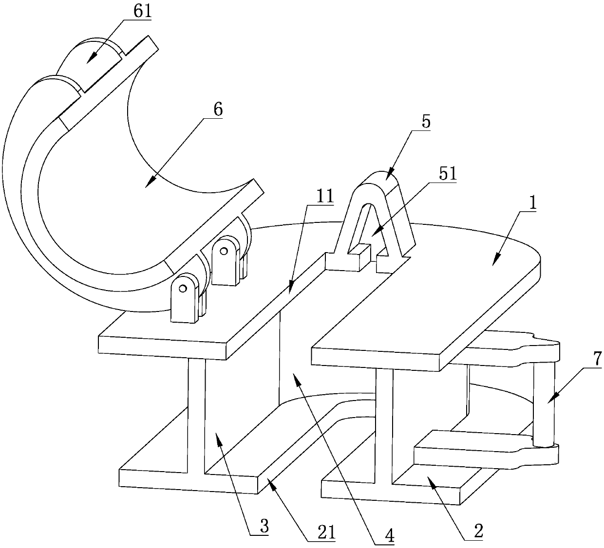
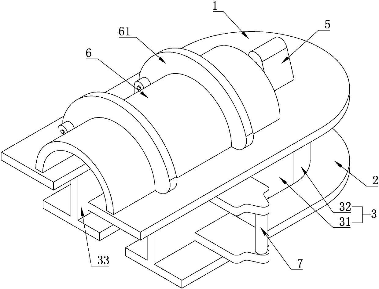
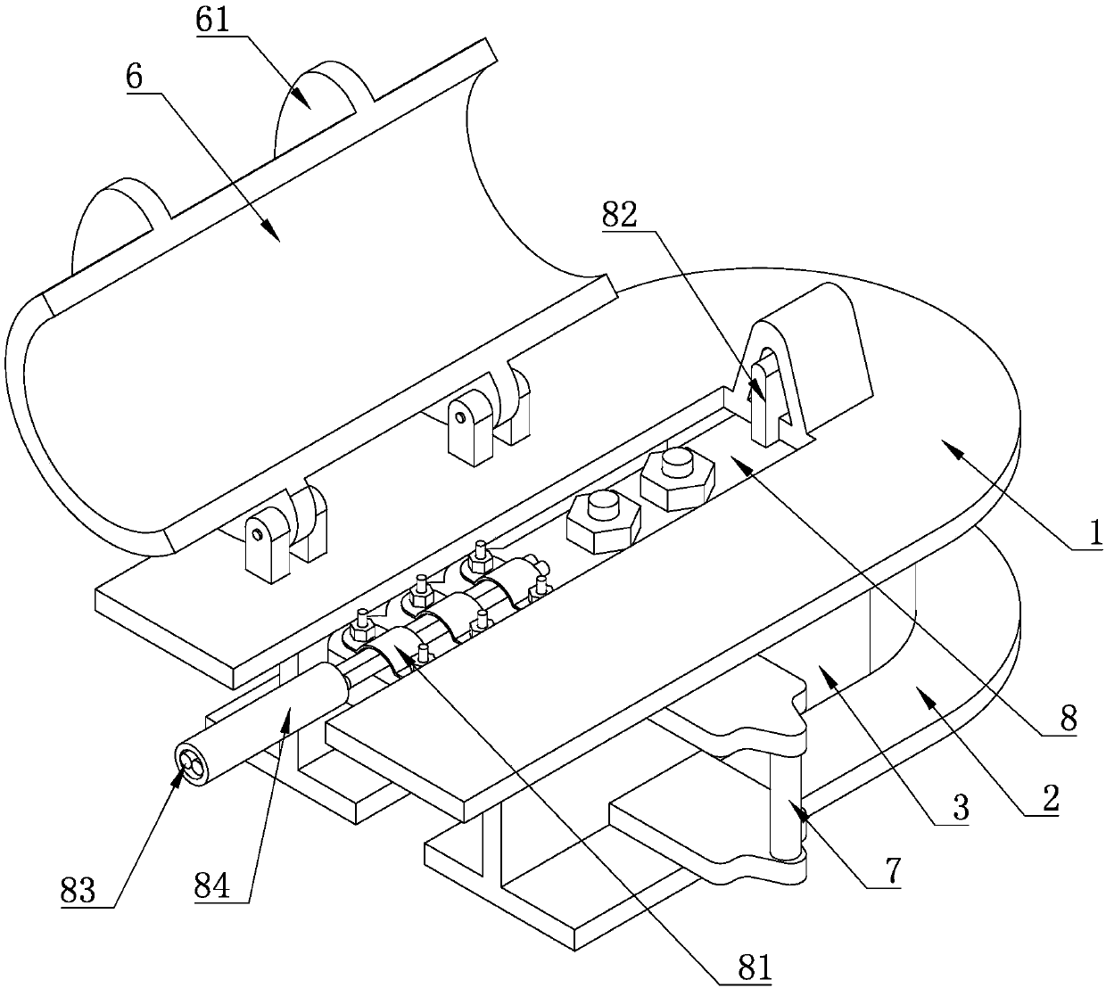
[0031] A special tool for live lapping of the switch on the pole, including a top plate 1, a bottom plate 2, and a side plate 3 connected between the top plate 1 and the bottom plate 2. The inner walls of the top plate 1, bottom plate 2, and side plate 3 are enclosed to accommodate the pile head of the upper lead wire. The cavity 4, the side plate 3 is a U-shaped plate, including two parallel flat plates 31 and an arc-shaped plate 32, one end of the two flat plates 31 is connected with the arc-shaped plate 32, and the other end forms an opening 33 communicating with the receiving chamber 4 and the outside world , one end of the flat plate 31 close to the opening 33 is aligned with the end of the bottom plate 2, the top plate 1 and the bottom plate 2 are respectively provided with a first installation groove 11 and a second installation groove 21 for the upper lead pile head to pass through, the first installation groove 11 and the second installation groove 21. The notch of the...

Embodiment 2

[0036] In this embodiment, a detachable structure is formed between the shielding cover 6 and the top plate 1, the cross section of the shielding cover 6 is arc-shaped, and a flange 61 is arranged on the outside of the shielding cover 6, and one end of the arc-shaped shielding The flange 61 is hinged with the top plate 1 .

[0037] When insulating and shielding the upper lead pile head of the switch on the column, the shielding cover 6 can be rotated relative to the top plate 1, so that the shielding cover 6 can be opened, and the shielding cover 6 is first opened along the hinge axis, and then closed after the installation Cover 6 is enough, open shielding cover 6, can observe the position of the wiring board of upper lead wire pile head through the first installation groove 11, also can determine whether there is the generation of damage situation, installation is more convenient and accurate; Flange 61 has strengthened shielding cover 6 strength and the contact area between...

Embodiment 3

[0039]The difference between the present embodiment and the second embodiment is that the shielding cover 6 is provided with a buckle, and the top plate 1 is provided with a slot that cooperates with the buckle.

[0040] When the shielding cover 6 is closed on the top plate 1, the buckle and the slot fit together so that the shielding cover 6 will not be easily opened under non-artificial conditions after the buckle, and the insulating shielding effect is better and more stable.


PUM


Abstract

The invention discloses a special tool for on-column switch live lap joint. The special tool comprises a top plate, a bottom plate, and a side plate connected between the top plate and the bottom plate. An accommodating cavity for accommodating an upper lead pile head is formed by inner walls of the top plate, the bottom plate and the side plate. The side plate is a U-shaped plate and comprises two parallel flat plates and a curved plate. One end of each of the two flat plates is connected to the other end of the arc-shaped plate to form an opening for communicating with the accommodating cavity and the outside. The top plate and the bottom plate are provided with a first mounting groove and second mounting groove through which the upper lead pile head passes. The orientation of the firstmounting groove and the second mounting groove is the same with the orientation of the side plate. The top plate is provided with a positioning convex block and a shielding cover which covers the first mounting groove. The positioning lug is provided with a positioning groove which communicates with the accommodating cavity. Through the accommodating cavity formed by the top plate, the bottom plate and the side plate, the effective insulating shielding of the upper lead pile head is realized, the isolation of wiring boards can be completed, and the operation is simple and convenient.

Description

technical field [0001] The invention belongs to the field of electrical equipment, and in particular relates to a special tool for live lapping of switches on poles. Background technique [0002] In the industry expansion project, there are mainly drop-out fuse lapping and pole-mounted switch lapping methods, in which the distance between the adjacent upper lead pile heads of the pole-mounted switch is relatively short, and the distance between adjacent upper lead pile heads is relatively short. If it does not meet the requirements of live work, it is necessary to take insulation and isolation measures between the upper lead pile heads of different phases. The upper lead pile head includes a terminal board and a clamping piece that clamps the lead wire with the terminal board. The clamping piece is connected by screws and nuts. The clamping piece is fixed on the terminal board, and the end of the terminal board away from the clamping piece is provided with a vertically upwar...

Claims


Application Information

Patent Timeline
Patent Type & Authority Applications(China)
IPC IPC(8): H02B3/00
CPCH02B3/00
Inventor 郑坤力陈捷林志龙黄斌杰崔敏杰史琪应鲁斌陆函奇曾志斌郑亮屠骅权鲍成杰舒雷谢宇传崔孟忠
Owner STATE GRID ZHEJIANG NINGBO YINZHOU POWER SUPPLY LTD CO
Learn More