
MEMS microphone

A technology of a microphone and a first diaphragm, applied in the field of sound and electricity, can solve the problems that the diaphragm cannot well characterize the sound pressure, reduce the vibration sensitivity of the diaphragm, affect the performance of the microphone, etc., so as to avoid the problem of diaphragm deflection, Guaranteed performance, the effect of reducing the sound resistance

Active Publication Date: 2018-03-23
WEIFANG GOERTEK MICROELECTRONICS CO LTD
View PDF4 Cites 22 Cited by
  • Summary
  • Abstract
  • Description
  • Claims
  • Application Information

AI Technical Summary

Problems solved by technology

[0006] In addition, the setting of the support column will lead to a large rigidity of the diaphragm, so that the diaphragm cannot well represent the state of the sound pressure, which reduces the sensitivity of the diaphragm vibration, thus affecting the performance of the microphone to the first degree

Method used


Image

  • MEMS microphone
  • MEMS microphone
  • MEMS microphone

Examples


Embodiment Construction

[0033] Various exemplary embodiments of the present invention will now be described in detail with reference to the accompanying drawings. It should be noted that the relative arrangements of components and steps, numerical expressions and numerical values ​​set forth in these embodiments do not limit the scope of the present invention unless specifically stated otherwise.

[0034] The following description of at least one exemplary embodiment is merely illustrative in nature and in no way taken as limiting the invention, its application or uses.

[0035] Techniques, methods and devices known to those of ordinary skill in the relevant art may not be discussed in detail, but where appropriate, such techniques, methods and devices should be considered part of the description.

[0036] In all examples shown and discussed herein, any specific values ​​should be construed as exemplary only, and not as limitations. Therefore, other instances of the exemplary embodiment may have dif...


PUM


Abstract

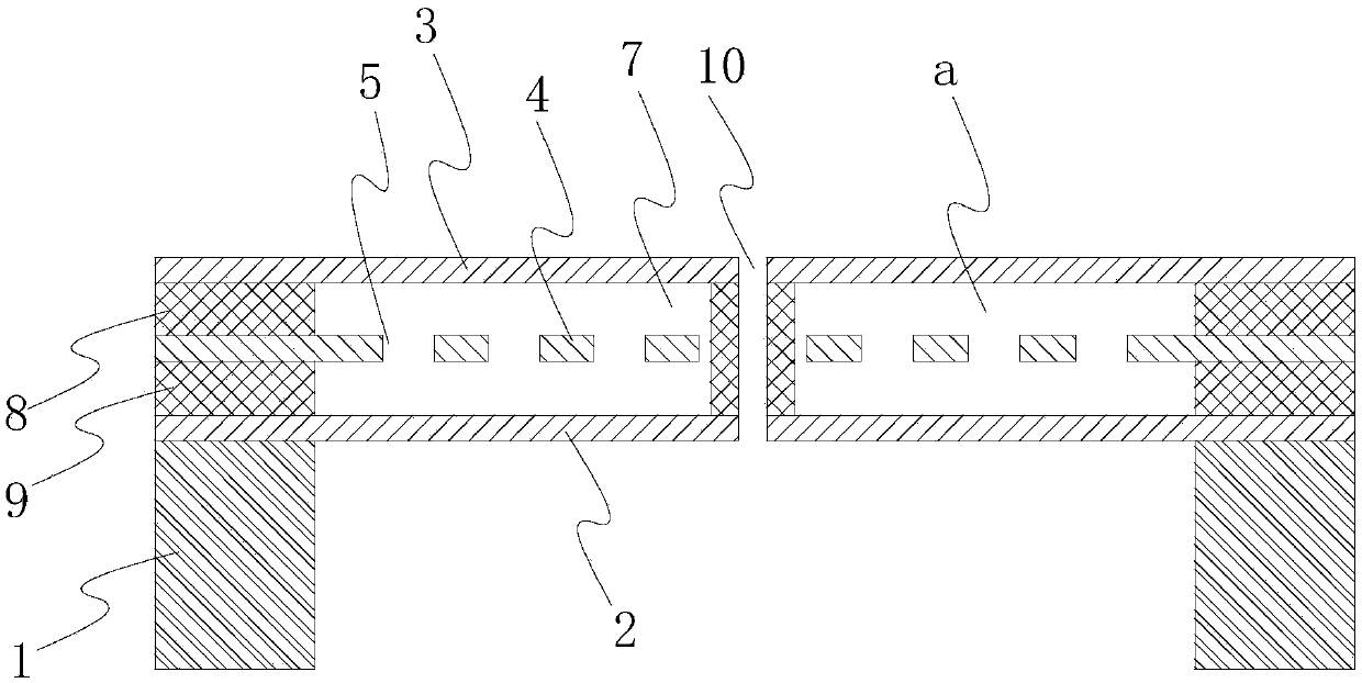
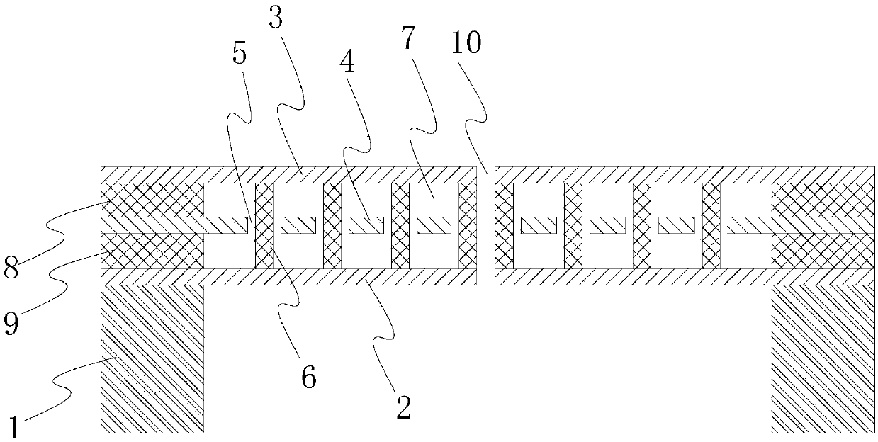
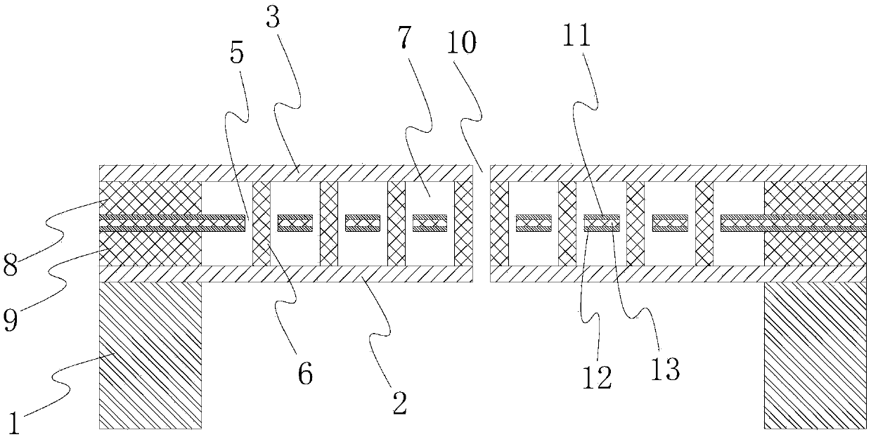
The invention discloses a MEMS microphone, which comprises a substrate, a first vibrating diaphragm and a second vibrating diaphragm. A sealing cavity is formed between the first vibrating diaphragm and the second vibrating diaphragm. A back electrode unit is arranged in the sealing cavity and forms a capacitor structure together with the first vibrating diaphragm and the second vibrating diaphragm. A plurality of through holes penetrating through the two sides of the back electrode unit are formed in the back electrode unit. A gas with the viscosity coefficient thereof smaller than that of air is filled in the sealing cavity. According to the MEMS microphone, the gas with the viscous coefficient thereof smaller than that of air is filled in the sealing cavity, so that the sound resistanceof the two vibrating diaphragms when the vibrating diaphragms are moving relative to the back electrode can be greatly reduced. The noise of the microphone is reduced. Meanwhile, the gas with the lowviscosity coefficient is used for filling, so that the pressure in the sealing cavity can be consistent with the pressure of the external environment. The problem of diaphragm deflection caused by differential pressure is avoided, and the performance of the microphone is guaranteed.

Description

technical field [0001] The present invention relates to the field of acoustic electricity, more specifically, to a microphone, especially to a MEMS microphone. Background technique [0002] MEMS (Micro-Electro-Mechanical Systems) microphones are microphones manufactured based on MEMS technology. The diaphragm and back pole are important components in MEMS microphones. The diaphragm and back pole constitute a capacitor integrated on a silicon wafer to realize the conversion of sound and electricity. . [0003] In traditional condenser microphones of this kind, in order to equalize the pressure between the diaphragm and the back electrode, through holes are usually arranged on the back electrode. But on the other hand, the through hole forms a capillary sound-absorbing structure similar to damping, which increases the acoustic resistance on the sound transmission path. An increase in acoustic resistance means an increase in the noise floor caused by airborne thermal noise, w...

Claims


Application Information

Patent Timeline
Patent Type & Authority Applications(China)
IPC IPC(8): H04R7/02H04R1/28
CPCH04R1/28H04R7/02H04R2201/003H04R19/005H04R19/04H04R1/04
Inventor 邹泉波王喆董永伟
Owner WEIFANG GOERTEK MICROELECTRONICS CO LTD
Learn More