
Cement floor polishing machine

A grinding machine and ground technology, which is applied to the parts of grinding machine tools, machine tools suitable for grinding workpiece planes, grinding heads, etc., can solve the problems of increased difficulty in ground grinding, floor deformation, leaving traces, etc. Large, increase the difficulty of grinding, and avoid the effect of touching the ground

Inactive Publication Date: 2018-03-27
陈卫
View PDF0 Cites 2 Cited by
  • Summary
  • Abstract
  • Description
  • Claims
  • Application Information

AI Technical Summary

Problems solved by technology

[0002] There are shadows of concrete floors everywhere around us, but the concrete floors are uneven before they are polished, which is neither beautiful nor hygienic, giving people a very cheap feeling, and it is very difficult to install the floor without polishing. It is easy to cause deformation of the floor, making the floor more ugly and inconvenient to clean, so it is necessary to polish the cement floor
[0003] Cement floor grinding not only has manual grinding by laborers, but also a machine specially designed for cement floor grinding. The cement floor grinding machine has the advantages of reducing the work intensity of laborers, improving the grinding efficiency, and making the ground more tidy; When the automatic cement floor grinder is working, the wheel is close to the ground, and it is easy to leave marks on the freshly polished cement floor, which increases the difficulty of ground grinding. Moreover, the grinding disc of the existing cement floor grinder is either round or blade. Limitations, can not be widely used in cement floors in different places

Method used


Image

  • Cement floor polishing machine
  • Cement floor polishing machine
  • Cement floor polishing machine

Examples


Embodiment Construction

[0028] The following will clearly and completely describe the technical solutions in the embodiments of the present invention with reference to the accompanying drawings in the embodiments of the present invention. Obviously, the described embodiments are only some, not all, embodiments of the present invention. Based on the embodiments of the present invention, all other embodiments obtained by persons of ordinary skill in the art without making creative efforts belong to the protection scope of the present invention.

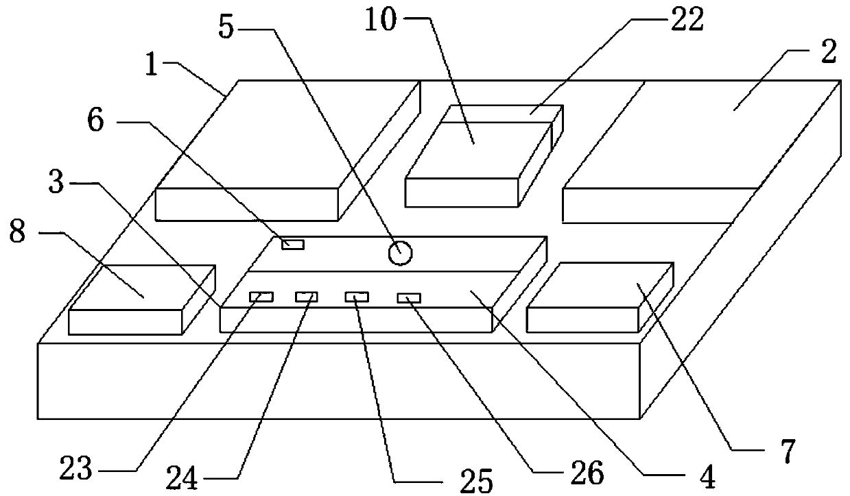
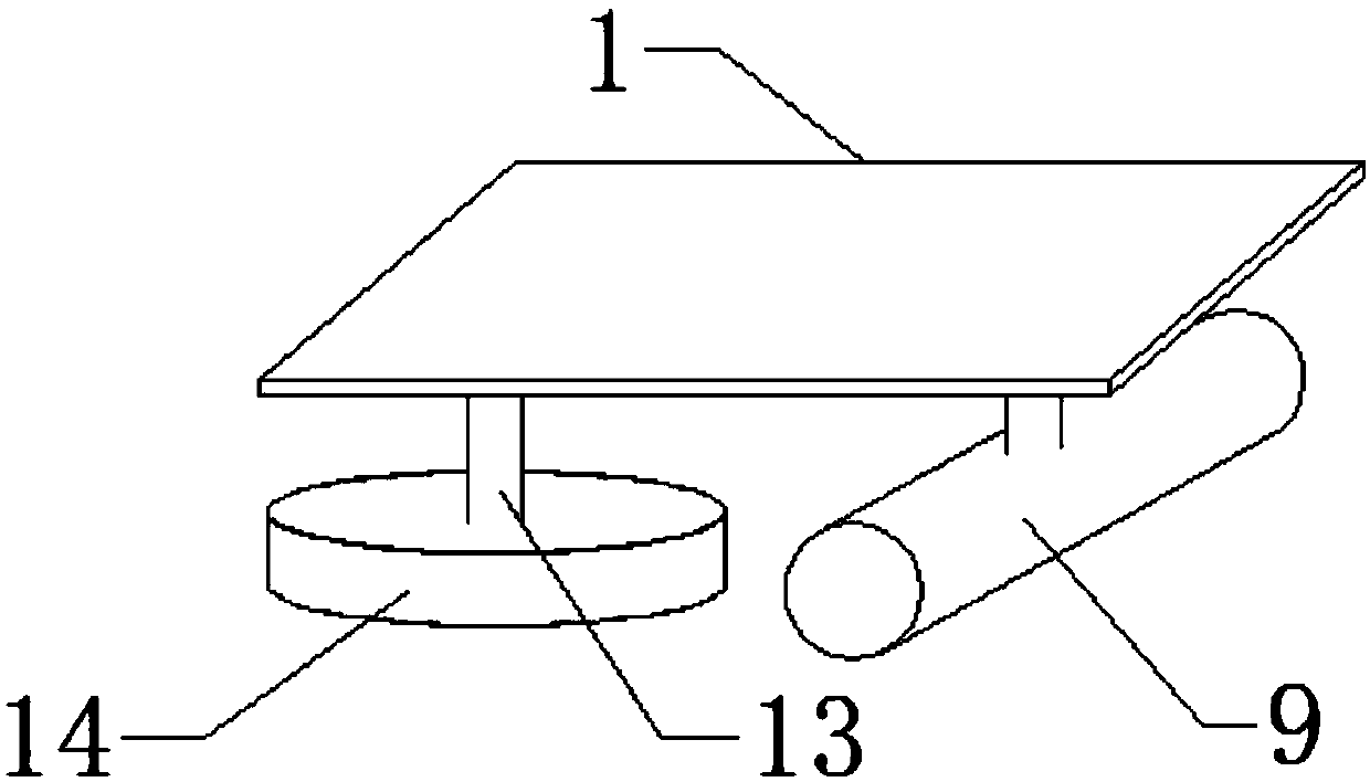
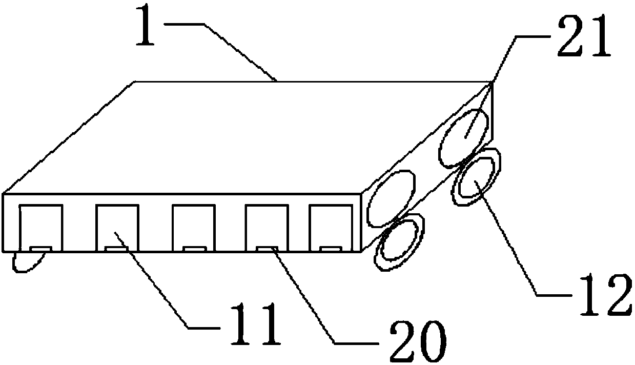
[0029] see Figure 1-5 , the present invention provides a technical solution: a cement floor grinding machine, including a base plate 1, a motor 2, a grinding disc 14 and a roller 9, the grinding disc 14 and the roller 9 are fixedly connected to the base plate 1 through a lifting device 13, and the base plate 1 is installed with The motor 2, the motor 2 connects the grinding disc 14 and the roller 9 through the shaft driving force, the grinding disc 14 include...


PUM


Abstract

The invention discloses a cement floor grinder, which comprises a bottom plate, a grinding disc and a machine wheel. The machine wheel is fixedly installed on the bottom of the base plate through a lifting device. A grinding disc and rollers are arranged in the middle of the machine wheel. The grinding disc and the fourth grinding disc, the grinding disc and the rollers are connected to the bottom plate through the lifting device; motors are installed on the bottom plate correspondingly, seats are arranged between the motors, and an operation console is vertically installed in front of the seats. The operation console includes switches, steering wheels and operation panels. Connect the steering wheel and the operation panel; there is a grinder around the bottom plate, an inner grinder is installed on the grinder, and a rotary knob is installed at one end of the grinder and the inner grinder, and the grinder and the inner grinder are movably connected to the base plate through the rotary knob. The cement floor grinder of the present invention is equipped with a grinding disc and a roller with a lifting device, so that the operation is simpler, the use is more labor-saving, the practicality is wide, the working intensity of the laborer can be reduced, the grinding disc can be protected, and the ground grinding efficiency can be improved.

Description

technical field [0001] The invention relates to the technical field of construction industry, in particular to a cement floor grinding machine. Background technique [0002] There are shadows of concrete floors everywhere around us, but the concrete floors are uneven before they are polished, which is neither beautiful nor hygienic, giving people a very cheap feeling, and it is very difficult to install the floor without polishing. It is easy to cause deformation of the floor, making the floor more ugly and inconvenient to clean, so it is necessary to polish the cement floor. [0003] Cement floor grinding not only has manual grinding by laborers, but also a machine specially designed for cement floor grinding. The cement floor grinding machine has the advantages of reducing the work intensity of laborers, improving the grinding efficiency, and making the ground more tidy; When the automatic cement floor grinder is working, the wheel is close to the ground, and it is easy t...

Claims


Application Information

Patent Timeline
Patent Type & Authority Applications(China)
IPC IPC(8): B24B7/18B24B41/00B24B41/04B24B27/00
CPCB24B7/18B24B27/0007B24B27/0076B24B41/00B24B41/047
Inventor 陈伟
Owner 陈卫
Learn More