Metalware polishing device

A technology for polishing devices and metal products, which is applied in the direction of grinding drive devices, metal processing equipment, grinding/polishing equipment, etc. It can solve the problems of deep polishing damage layer, low polishing rate, and reduced efficiency, so as to speed up work efficiency, Improved productivity and simple structure

Inactive Publication Date: 2018-03-27
常熟国球包装材料有限公司
View PDF0 Cites 1 Cited by
  • Summary
  • Abstract
  • Description
  • Claims
  • Application Information

AI Technical Summary

Problems solved by technology

[0002] The polishing device is also called a grinding machine, which is often used for mechanical grinding, polishing and waxing. Its working principle is: the motor drives the sponge or wool polishing disc installed on the polishing machine to rotate at a high speed. Friction on the surface to be polished can achieve the purpose of removing paint surface pollution, oxide layer, and shallow marks. The speed of the polishing disc is generally 1500-3000 r / min, mostly continuously variable, and can be adjusted at any time during construction. Polishing The key to the operation of the machine is to try to get the maximum polishing rate so that the damaged layer produced during polishing can be removed as soon as possible, and at the same time, the damaged layer of polishing will not affect the final observed tissue, that is, it will not cause false tissue. The former requires the use of Coarse abrasives to ensure a greater polishing rate to remove the polished damage layer, but the polishing damage layer is also deeper; the latter requires the use of the finest material to make the polishing damage layer shallower, but the polishing rate is low, However, the current polishing equipment needs to be placed on the polishing device with manual assistance, and after the polishing is completed, the machine needs to be stopped to take out the product, which reduces efficiency and wastes time. For this reason, we propose a metal product polishing device. solve the above problems

Method used


Image

  • Metalware polishing device
  • Metalware polishing device
  • Metalware polishing device

Examples


Embodiment Construction

[0016] The following will clearly and completely describe the technical solutions in the embodiments of the present invention with reference to the accompanying drawings in the embodiments of the present invention. Obviously, the described embodiments are only some, not all, embodiments of the present invention.

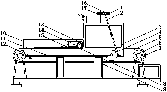
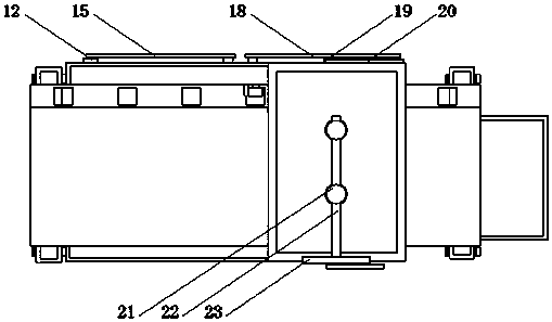
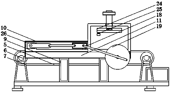
[0017] refer to Figure 1-3 , a metal product polishing device, including a base, the four corners of the upper end of the base are provided with brackets 7, which are convenient for fixing, and two brackets 7 on the same side form a group, and a rotating shaft 6 is arranged between the two brackets 7 of the same group , the two rotating shafts 6 are connected through the rotation of the conveyor belt 5, which is convenient to move, and one side of the conveyor belt 5 is provided with a limit hole, the upper end of the base is fixed with four support blocks 9, and the upper ends of the four support blocks 9 are jointly fixed with a partition 11. Stable support, and t...


PUM


Abstract

The invention discloses a metal product polishing device, which comprises a base. The four corners of the upper end of the base are provided with brackets, and two brackets on the same side form a group, and a rotating shaft is arranged between the two brackets of the same group. The rotating shafts are rotatably connected by a conveyor belt, and a limit hole is provided on one side of the conveyor belt. Four support blocks are fixed on the upper end of the base, and a partition is fixed on the upper ends of the four support blocks, and the bottom surface of the partition and the conveyor belt In case of conflict, a bearing plate is fixed on one side of the upper end of the partition. The invention realizes the automatic polishing and moving of the product, solves the problem that the general polishing device still needs manual assistance, the product is placed on the polishing device, the machine is shut down after the polishing is completed and the product is removed, and the product automation is realized Polishing speeds up work efficiency, improves productivity, has a simple structure, is convenient to operate, and is suitable for popularization.

Description

technical field [0001] The invention relates to the technical field of metal polishing, in particular to a metal product polishing device. Background technique [0002] The polishing device is also called a grinding machine, which is often used for mechanical grinding, polishing and waxing. Its working principle is: the motor drives the sponge or wool polishing disc installed on the polishing machine to rotate at a high speed. Friction on the surface to be polished can achieve the purpose of removing paint surface pollution, oxide layer, and shallow marks. The speed of the polishing disc is generally 1500-3000 r / min, mostly continuously variable, and can be adjusted at any time during construction. Polishing The key to the operation of the machine is to try to get the maximum polishing rate so that the damaged layer produced during polishing can be removed as soon as possible, and at the same time, the damaged layer of polishing will not affect the final observed tissue, tha...

Claims


Application Information

Patent Timeline
Patent Type & Authority Applications(China)
IPC IPC(8): B24B29/02B24B41/02B24B41/06B24B41/00B24B47/12B24B27/033
CPCB24B29/02B24B27/033B24B41/005B24B41/02B24B41/06B24B47/12
Inventor 吴新华
Owner 常熟国球包装材料有限公司
Why Eureka
Try Eureka