
Two-dimensional laser dynamic detection device and method of steel rail profiles and corrugations

A two-dimensional laser and detection device technology, applied to measuring devices, optical devices, railway vehicle shape measuring devices, etc., can solve the problems of low detection efficiency, poor reliability of measurement data, time-consuming and labor-intensive problems

Active Publication Date: 2018-03-27
CENT SOUTH UNIV
View PDF8 Cites 18 Cited by
  • Summary
  • Abstract
  • Description
  • Claims
  • Application Information

AI Technical Summary

Problems solved by technology

Although the efficiency of indirect measurement is high, the detection accuracy is easily affected by the driving speed and wheel tread, resulting in poor reliability of measurement data
[0006] In summary, the current domestic rail profile detection methods are mainly based on static detection, the detection efficiency is low, and the measurement accuracy is difficult to guarantee, and the static detection can only obtain the profile data of the current rail section, and it is difficult to analyze the rail profile in a certain interval. Comprehensive analysis of shape deviation or wear
However, the current corrugation detection method mainly adopts the static method for direct measurement, and the detection efficiency is low. Although the indirect measurement adopts the dynamic method, it is difficult to meet the expected detection requirements.
At the same time, the current domestic rail profile detection method and corrugation detection method are independent of each other and need to be carried out step by step, which is time-consuming and laborious

Method used


Image

  • Two-dimensional laser dynamic detection device and method of steel rail profiles and corrugations
  • Two-dimensional laser dynamic detection device and method of steel rail profiles and corrugations
  • Two-dimensional laser dynamic detection device and method of steel rail profiles and corrugations

Examples


Embodiment Construction

[0093] The technical solution of the present invention will be further described below in conjunction with the accompanying drawings.

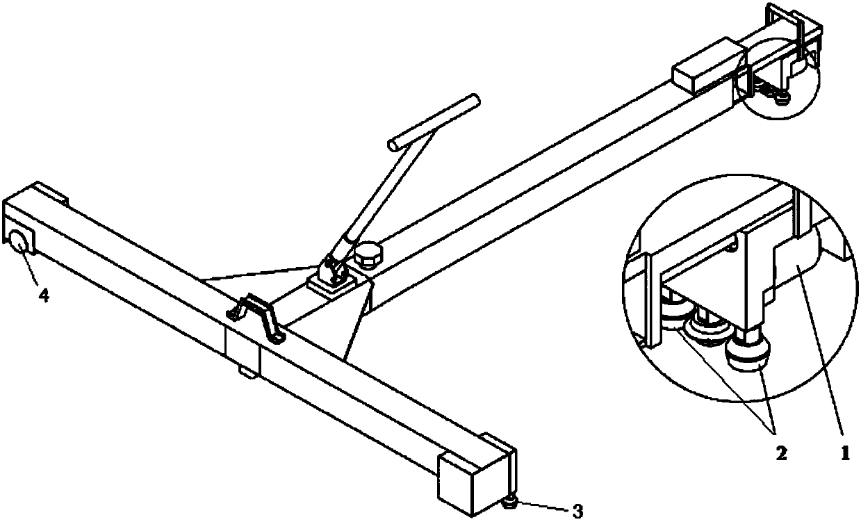
[0094] see Figure 15 , the detection device of this embodiment includes a two-dimensional laser displacement sensor, an adjustable bracket, a traveling trolley, a DC power supply, an encoder, an industrial computer, and rail profile detection software. The traveling trolley is composed of T-shaped structural parts, traveling wheels, and guide wheels. Its main function is to carry a two-dimensional laser displacement sensor to realize longitudinal movement along the rail.

[0095] When the device of this embodiment detects the profile of the rail, it includes the following processes:

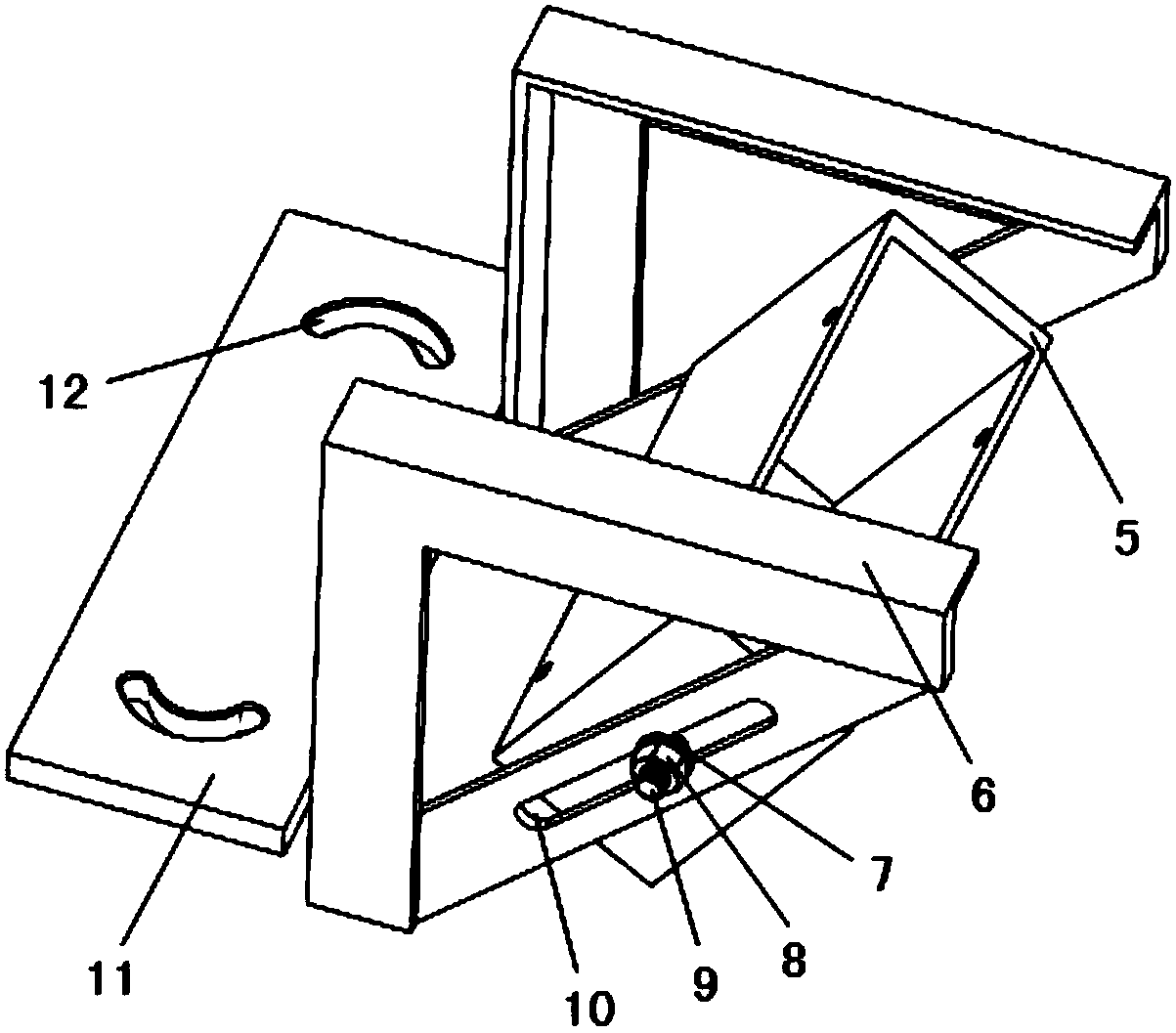
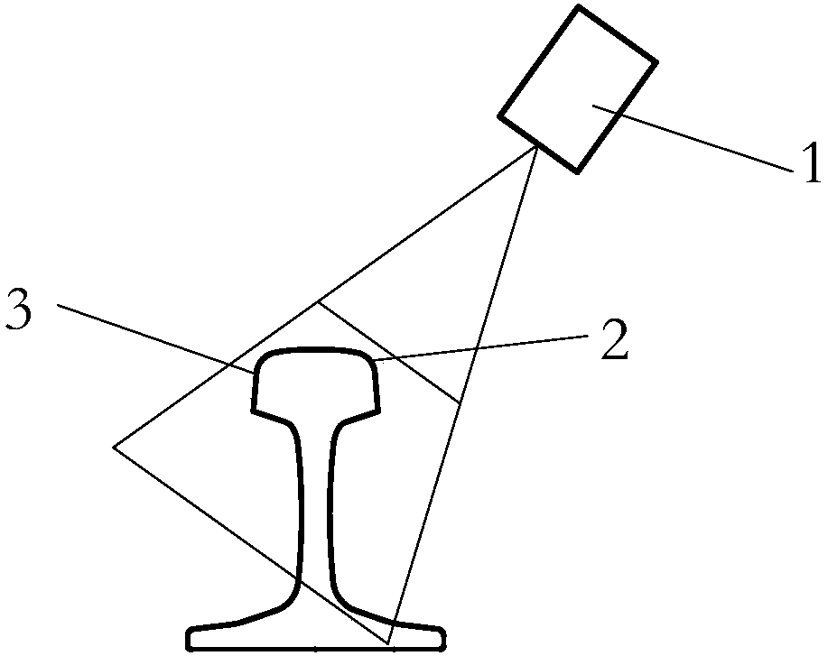
[0096] 1) The adjustable bracket is fixed on the trolley through the fixing plate and screws. When working, the two-dimensional laser displacement sensor is placed in the installation box, and the laser plane of the two-dimensional laser displacement sensor is ...


PUM


Abstract

The invention discloses a two-dimensional laser dynamic detection device and method of steel rail profiles and corrugations. A two-dimensional laser displacement sensor is adopted to collect steel rail profile initial-data, and fixed on a walking trolley through an adjustable bracket. The walking trolley is composed of a T-shaped structural component, a walking wheel, a positioning wheel and a guide wheel, and mainly used for carrying the two-dimensional laser displacement sensor and achieving longitudinal movements along a steel rail. A coder coaxially connected with the walking wheel of thewalking trolley is used for recording the walking position of the walking trolley. Then, a series of analytical processing is conducted on the steel rail profile initial-data collected by the two-dimensional laser displacement sensor so as to complete profile deviation calculation of the steel rail profiles and corrugation analysis. The detection device can not only conduct steel rail profile dynamic-continuous-detection on a specified interval, but also conduct static detection on the steel rail profile of a specified position, and has the advantages of complete detection functions, high efficiency and the like.

Description

technical field [0001] The invention relates to the technical field of rail transportation and measurement, in particular to a two-dimensional laser dynamic detection device and method for rail profile and corrugation. Background technique [0002] Excellent rail profile is the premise and guarantee for safe and smooth driving. As the running speed of the train increases significantly and the load continues to increase, the interaction force between the rail and the wheel increases, and the wear on the surface of the rail increases day by day, which makes the profile of the rail section gradually deviate from the standard profile, and the longitudinal direction of the rail will also produce rail damage. Wavy wear (wave grinding). [0003] At present, the profile detection of rail section in domestic application mainly adopts static detection method, and its specific detection methods can be divided into two categories: contact type and non-contact type. The contact rail se...

Claims


Application Information

Patent Timeline
Patent Type & Authority Applications(China)
IPC IPC(8): B61K9/08G01B11/00G01B11/14G01B11/24
CPCB61K9/08G01B11/00G01B11/14G01B11/24
Inventor 杨岳易兵陈峰罗意平李雄兵卢瑶戴万林王攀攀刘龙
Owner CENT SOUTH UNIV
Learn More