
Large-tonnage steel box girder pushing device, pushing system and pushing method

A technology of a jacking device and a steel box girder, which is applied in the directions of bridges, bridge construction, erection/assembly of bridges, etc., can solve the problem that it is difficult to control the steel box girder to stop at the target position, so as to improve the jacking and moving efficiency, improve the The effect of stability

Pending Publication Date: 2018-03-27
CHINA RAILWAY ERJU 5TH ENG +1
View PDF10 Cites 16 Cited by
  • Summary
  • Abstract
  • Description
  • Claims
  • Application Information

AI Technical Summary

Problems solved by technology

[0004] The object of the present invention is to provide a large-tonnage steel box girder for the problems that the steel box girder itself has leapfrogs and it is difficult to control the steel box girder to stop at the target position when the steel box girder is moved as a whole by the dragging method in the prior art. A box girder jacking device, a jacking system and a jacking method, the steel box girder jacking device is a three-dimensional control device including three telescopic devices, and the three telescopic devices are respectively arranged in three directions in a three-dimensional coordinate system, The movement of the steel box girder is promoted through the expansion and contraction of the oil cylinder, and the entire steel box girder can be pushed to the designed position accurately, and the deviation can be corrected during the pushing process, without the need for a slide beam. The steel box girder pushing device is small and flexible, Easy to use and effective

Method used


Image

  • Large-tonnage steel box girder pushing device, pushing system and pushing method
  • Large-tonnage steel box girder pushing device, pushing system and pushing method
  • Large-tonnage steel box girder pushing device, pushing system and pushing method

Examples


Embodiment 1

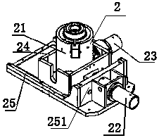
[0061] Such as Figure 1-5 As shown, the large-tonnage steel box girder pushing device 2 includes jacking telescopic equipment for jacking up the steel box girder 1, flat push telescopic equipment for pushing the steel box girder 1 to move to the target position, and deviation correcting telescopic equipment, The jacking equipment, flat push telescopic equipment and deviation correcting telescopic equipment are all installed on the sliding box body 24, and the bottom of the sliding box body 24 is provided with a sliding base 25 for sliding, and the horizontal pushing telescopic equipment, deviation correcting telescopic equipment The opposite ends of the equipment are connected to the sliding box body 24 and the sliding base 25 respectively, so that the sliding base 25 and the sliding box body 24 can move relatively. The jacking telescopic equipment is a jacking cylinder 21. The horizontal pushing telescopic equipment is a horizontal pushing oil cylinder 22, and the deviation ...

Embodiment 2

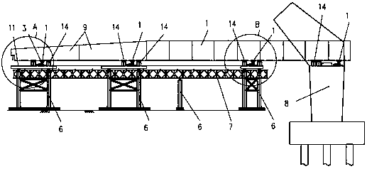
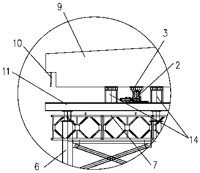
[0067] Such as Figure 1-5As shown, the large-tonnage steel box girder pushing system includes a plurality of supports 6 and equipment platforms 7 installed on the plurality of supports 6, and the supports 6 are erected on the route where the steel box girder 1 moves to the target position. The above-mentioned pushing device 2 is installed on the top of each support 6 and the abutment 8, and the pushing device 2 is installed on the top of a plurality of supports 6, thereby forming a plurality of pushing devices 2 to simultaneously press the steel box The beam 1 completes the jacking, which avoids the problem of unbalanced force on the steel box girder 1 due to the partial installation of the jacking device, which makes the overall force of the steel box girder 1 more balanced, and reduces the weight of each jacking device. 2 The load carried.

[0068] Since the steel box girder 1 is constantly moving towards the target position during the pushing process, the front end of the...

Embodiment 3

[0081] Such as Figure 6-9 As shown, the large-tonnage steel box girder pushing method, when using the pushing device 2 in the embodiment 1 to push the steel box girder 1, the jacking telescopic equipment, flat pushing telescopic equipment and The deviation correcting telescopic equipment is respectively set as jacking cylinder 21, flat pushing cylinder 22 and deviation correcting cylinder 23, and the pushing is completed according to the following steps:

[0082] a. Jack up the steel box girder 1, open the jacking oil cylinder 21, so that the jacking oil cylinder 21 rises and lifts the steel box girder 1 away from the support seat 14;

[0083] b. Push the steel box girder 1, open the horizontal push cylinder 22, so that the steel box girder 1 and the sliding box body 24 move forward as a whole, until the horizontal push cylinder 22 completes a stroke;

[0084] c. The jacking device 2 is reset, and the jacking cylinder 21 is opened to lower the steel box girder 1 as a whole u...


PUM


Abstract

The invention relates to the technical field of bridge construction equipment and in particular relates to a large-tonnage steel box girder pushing device, a pushing system and a pushing method. The pushing device comprises jacking expansion equipment, translational expansion equipment and correction expansion equipment, wherein the jacking equipment, the translational expansion equipment and thecorrection expansion equipment are arranged on a sliding box; a sliding base used for sliding is arranged at the bottom of the sliding box; and two opposite expansion ends of the translational expansion equipment and the correction expansion equipment are respectively connected to the sliding box and the sliding base, so that the sliding base and the sliding box can move relative to each other. The three expansion devices of the steel box girder pushing device are respectively arranged in three directions of a three-dimensional coordinate system. By virtue of movements of expanding the cylinder and pushing the steel box girder, the steel box girder can be wholly accurately pushed to the designed positions, correction can be realized in the pushing process, and a slide beam is not needed. The steel box girder pushing deice is small, flexible, convenient to use and effective.

Description

technical field [0001] The invention relates to the technical field of bridge construction equipment, in particular to a large-tonnage steel box girder jacking device, a jacking system and a jacking method. Background technique [0002] The construction techniques of bridges are diverse and cover all aspects, and the installation and positioning of steel box girders are the most important links. In the construction process of steel box girders, due to the complexity of the site, such as crossing expressways, crossing city railways, crossing high-speed rails, crossing ports with navigation requirements, and arteries with safety driving requirements, etc., it is affected by this complex site and Due to the influence of working conditions, in order to ensure the safety of construction, it is necessary to assemble the steel box girder in a safe place, and then move the steel box girder to the designed target position as a whole. [0003] At present, for the construction process...

Claims


Application Information

Patent Timeline
IPC IPC(8): E01D21/06E01D2/04
CPCE01D2/04E01D21/06
Inventor 陈金果邓威杨都杨刚
Owner CHINA RAILWAY ERJU 5TH ENG
Learn More