Flying dust monitoring device for construction monitoring

A monitoring device and building technology, applied in the direction of measuring devices, supporting machines, instruments, etc., can solve the problems of complicated operation, poor monitoring effect, and time-consuming dust emission.

Inactive Publication Date: 2018-03-27
查宇
View PDF7 Cites 19 Cited by
  • Summary
  • Abstract
  • Description
  • Claims
  • Application Information

AI Technical Summary

Problems solved by technology

[0006] In order to overcome the shortcomings in the prior art that the monitoring of dust takes a lot of time, the operation is complicated, and the monitoring effect is not good, the technical problem to be solved by the invention is to provide a time-saving, simple operation, and better monitoring effect. Good dust monitoring device for building monitoring

Method used


Image

  • Flying dust monitoring device for construction monitoring
  • Flying dust monitoring device for construction monitoring
  • Flying dust monitoring device for construction monitoring

Examples


Embodiment 1

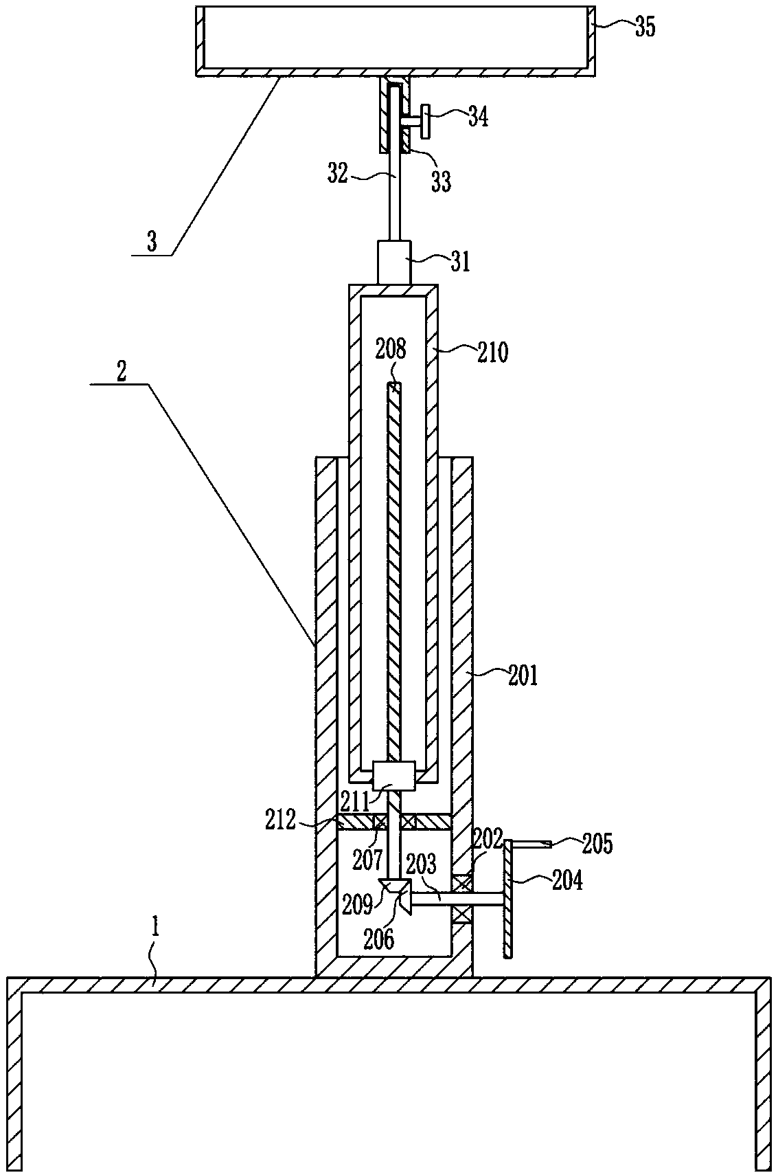
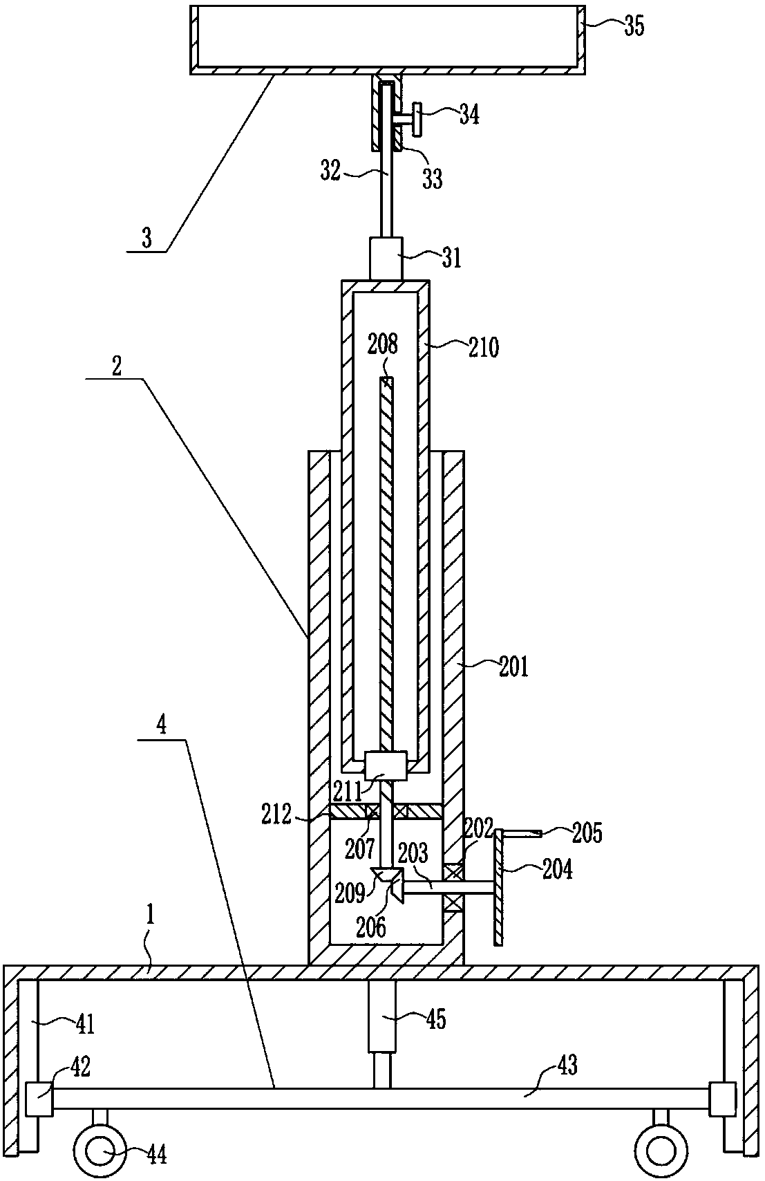
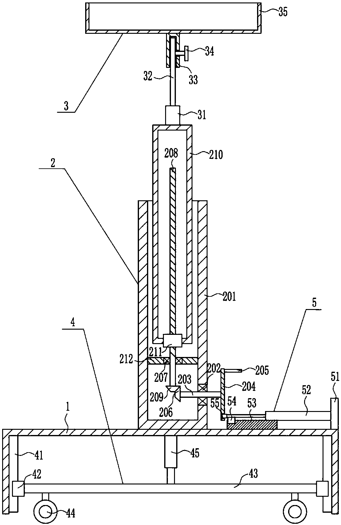
[0037] A dust monitoring device for building monitoring, such as Figure 1-6 As shown, it includes a frame 1, a lifting device 2 and a monitoring device 3. The lifting device 2 is provided in the middle of the top of the frame 1, and the monitoring device 3 is provided on the lifting part of the lifting device 2.

Embodiment 2

[0039] A dust monitoring device for building monitoring, such as Figure 1-6 As shown, it includes a frame 1, a lifting device 2 and a monitoring device 3. The lifting device 2 is provided in the middle of the top of the frame 1, and the monitoring device 3 is provided on the lifting part of the lifting device 2.

[0040] The lifting device 2 includes a first sleeve 201, a first bearing seat 202, a first rotating shaft 203, a turntable 204, a rotating rod 205, a first bevel gear 206, a second bearing seat 207, a screw mandrel 208, and a second bevel gear 209 , a hollow tube 210, a nut 211 and a horizontal plate 212, a first sleeve 201 is vertically arranged in the middle of the top of the frame 1, and a first bearing seat 202 is embedded in the lower part of the right side of the first sleeve 201, and the first bearing seat 202 The inner bearing is connected with the first rotating shaft 203, the right end of the first rotating shaft 203 is located outside the first sleeve 201...

Embodiment 3

[0042] A dust monitoring device for building monitoring, such as Figure 1-6 As shown, it includes a frame 1, a lifting device 2 and a monitoring device 3. The lifting device 2 is provided in the middle of the top of the frame 1, and the monitoring device 3 is provided on the lifting part of the lifting device 2.

[0043] The lifting device 2 includes a first sleeve 201, a first bearing seat 202, a first rotating shaft 203, a turntable 204, a rotating rod 205, a first bevel gear 206, a second bearing seat 207, a screw mandrel 208, and a second bevel gear 209 , a hollow tube 210, a nut 211 and a horizontal plate 212, a first sleeve 201 is vertically arranged in the middle of the top of the frame 1, and a first bearing seat 202 is embedded in the lower part of the right side of the first sleeve 201, and the first bearing seat 202 The inner bearing is connected with the first rotating shaft 203, the right end of the first rotating shaft 203 is located outside the first sleeve 201...


PUM


Abstract

The invention relates to a monitoring device, in particular to a flying dust monitoring device for construction monitoring. The technical effects that the provided flying dust monitoring device for construction monitoring is capable of saving time, easy to operate and good in monitoring effect are achieved. In order to achieve the technical effects, the provided flying dust monitoring device for construction monitoring comprises a frame and the like. A lifting device is arranged in the middle of the top of the frame. A monitoring device body is arranged on a lifting part of the lifting device.The height of the monitoring device body is adjusted through the lifting device, a left-right movement device is further arranged, thus, the monitoring device is moved more conveniently, and the effects that time is saved, operation is simple and the monitoring effect is good are achieved.

Description

technical field [0001] The invention relates to a monitoring device, in particular to a dust monitoring device for building monitoring. Background technique [0002] Architecture is the general term for buildings and structures, and it is an artificial environment created by people using the material and technological means they have mastered, and using certain scientific laws, feng shui concepts, and aesthetic principles to meet the needs of social life. [0003] Flying dust is an open pollution source that enters the atmosphere due to the dust on the ground being driven by wind, man-made or other drives, and is an important part of the total suspended particulate matter in the ambient air. [0004] There is often dust during construction on the construction site, which seriously affects people's normal activities and pollutes the environment. In the prior art, the monitoring of dust takes a lot of time, the operation is complicated, and the monitoring effect is not good. T...

Claims


Application Information

Patent Timeline
Patent Type & Authority Applications(China)
IPC IPC(8): F16M11/28F16M11/18F16M11/04G01N15/04G01N15/06
CPCF16M11/28F16M11/045F16M11/18G01N15/04G01N15/06G01N15/0606G01N15/0637G01N2015/0096
Inventor 查宇曾成力邝运明
Owner 查宇
Why Eureka
Try Eureka