
Method for automatically inserting logic supports and hangers in pipeline design

A technology of pipeline design and automatic insertion, applied in computer-aided design, design optimization/simulation, calculation, etc., can solve the overall problems of reducing work efficiency, time-consuming process of positioning logical support and hanger, and unfavorable to the design level of pipeline support and hanger. Improve and other issues to achieve the effect of reducing design errors and improving design efficiency

Active Publication Date: 2018-03-27
四川电力设计咨询有限责任公司
View PDF5 Cites 2 Cited by
  • Summary
  • Abstract
  • Description
  • Claims
  • Application Information

AI Technical Summary

Problems solved by technology

The disadvantages of this method are: 1. Different designers have different understandings of the positioning of the support and hanger, which is reflected in completely different design schemes, which will lead to repeated revisions of the positioning of the support and hanger during the design process, reducing the workload. Efficiency; 2. For some huge piping systems, there are dozens or even hundreds of supports and hangers, and the process of locating logical supports and hangers takes a long time; 3. It is not conducive to the standardized development of positioning logical supports and hangers. The overall improvement of the design level of pipe supports and hangers; 4. The positioning errors of all logical supports and hangers are completely checked by the designers according to their own experience and ability, and it is impossible to guarantee that all the logical supports and hangers are positioned to meet the specification requirements or the unified requirements of the design unit

Method used


Image

  • Method for automatically inserting logic supports and hangers in pipeline design
  • Method for automatically inserting logic supports and hangers in pipeline design
  • Method for automatically inserting logic supports and hangers in pipeline design

Examples


Embodiment Construction

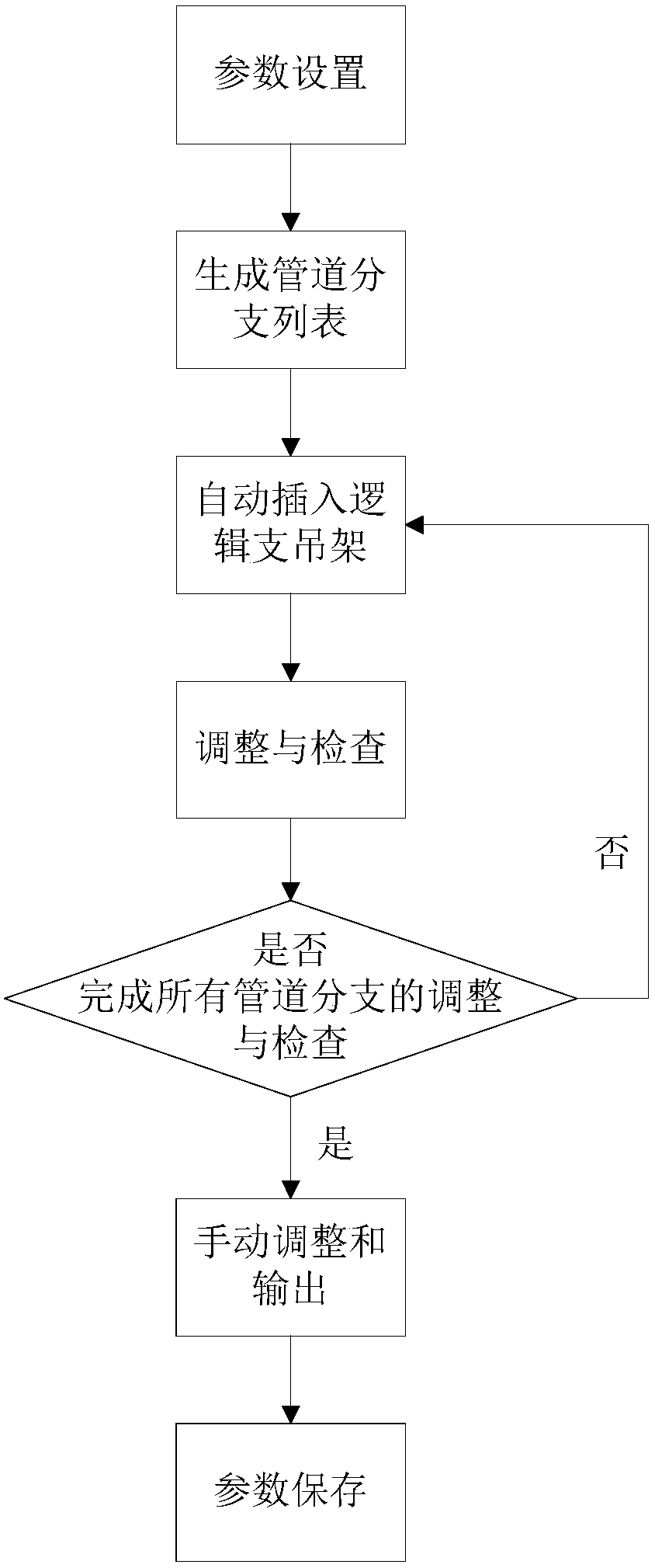
[0026] Such as figure 1 The method for automatically inserting the logic support and hanger in the pipeline design of the present invention shown includes:

[0027] A. Parameter setting: read the current optimal parameter scheme and alternative scheme from the parameter library, the parameters include the adjustment coefficient K of the support and hanger spacing and the coefficient K1~K7 for checking whether the support and hanger setting is reasonable, and the support and hanger spacing The initial value of the adjustment coefficient K is 0.9. The parameters specifically include:

[0028] L0: Maximum spacing of horizontal straight pipe supports and hangers:

[0029] According to the formula for the maximum horizontal distance between supports and hangers of straight pipe sections without concentrated load in "DL / T5054-2016 Code for Design of Steam and Water Pipelines in Thermal Power Plants", that is, the horizontal straight pipe supports and hangers calculated from formul...


PUM


Abstract

The invention relates to a method for automatically inserting logic supports and hangers in pipeline design. The method includes the steps of A, setting parameters, to be more specific, reading a currently optimal parameter scheme and an alternative scheme from a parameter library; B, selecting pipeline branch insertion key points to form a pipeline branch list; C, automatically inserting the automatically inserting the logic supports and hangers in each pipeline branch; D, regulating the spacing adjustment coefficients of the supports and hangers to regulate the distance between the support and hanger insertion points and adjacent elements, and inspecting each pipeline branch; E, manually regulating and outputting, to be more specific, reading the errors of each pipeline branch, and generating inspection reports; F, saving parameters, to be more specific, recalculating all parameters in the parameter setting, and generating a new optimal parameter scheme. By the method, automatic insertion, regulation and verification of the logic supports and hangers can be achieved, the design efficiency of the logic supports and hangers is increased greatly, manual design errors are reduced greatly, and a fast and uniform design scheme can be formed.

Description

technical field [0001] The invention relates to pipeline design, in particular to a method for automatically inserting logical supports and hangers in pipeline design. Background technique [0002] Supports and hangers play the role of bearing pipeline loads, bearing various accidental loads or additional loads, limiting pipeline displacement and controlling pipeline vibration in the pipeline system. In pipeline design, after completing the pipeline system design and layout design, the support and hanger design must be completed to ensure the safe and stable operation of the pipeline. Since the design of supports and hangers is located downstream of the entire pipeline design process, its design results are greatly affected by the upstream process. Usually a small change in the system design or layout design will lead to a major change in the design of the support and hanger. In the entire pipeline design process, the design changes of supports and hangers are often the mo...

Claims


Application Information

Patent Timeline
Patent Type & Authority Applications(China)
IPC IPC(8): G06F17/50
CPCG06F30/17G06F30/20G06F2113/14
Inventor 刘晓伟陈超文剑胡商建苑媛程月杨敏王梦怡相红阳吴迪安军袁文薛浩王怡
Owner 四川电力设计咨询有限责任公司
Learn More