Quick connector for optical fiber installation

An installation and connector technology, applied in the direction of light guide, optics, instruments, etc., can solve the problems of complicated operation and many carrying tools.

Pending Publication Date: 2022-07-05
安徽扬子实业有限公司
View PDF0 Cites 0 Cited by
  • Summary
  • Abstract
  • Description
  • Claims
  • Application Information

AI Technical Summary

Problems solved by technology

[0005] The purpose of the present invention is to provide a quick connector for optical fiber installation, which has the advantages of convenient operation and solves the problems of complicated operation and many carrying tools in the prior art

Method used


Image

  • Quick connector for optical fiber installation
  • Quick connector for optical fiber installation
  • Quick connector for optical fiber installation

Examples


Embodiment 1

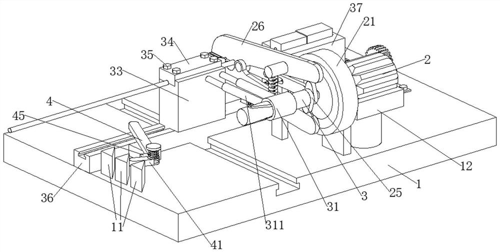
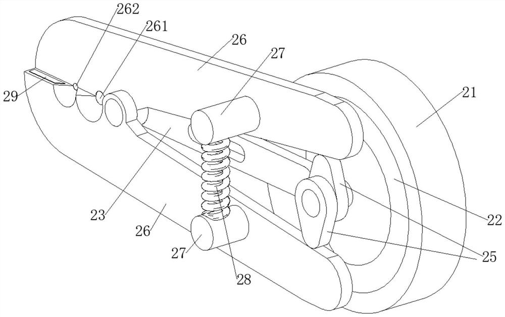
[0028] The present invention provides a technical solution: a quick connector for optical fiber installation, comprising a mounting plate 1, a base 12 is fixedly connected to the mounting plate 1, a motor 2 is fixedly connected to the base 12, and an output end of the motor 2 is fixedly connected There is a disc 21, two symmetrically arranged expansion cams 25 are fixedly connected to the disc 21, a column 5 is fixedly connected to the mounting plate 1, a horizontal plate 23 is slidably connected to the column 5, and a slider is fixedly connected to the horizontal plate 23. 24. The disc 21 is provided with a chute 22 that cooperates with the slider 24, the horizontal plate 23 is rotatably connected with two clamping plates 26 that cooperate with each other, and the two clamping plates 26 are fixedly connected with mounting posts 27. A tension spring 28 is fixedly connected between the 27, the two expansion cams 25 are alternately abutted against the two clamping plates 26, and ...

Embodiment 2

[0031] On the basis of the first embodiment, further, the mounting plate 1 is provided with a fixing mechanism for fixing the optical fiber. The fixing mechanism includes a rectangular bar 36 slidably connected to the mounting plate 1, and a locking block 33 is slidably connected to the rectangular bar 36. , a pressure plate 34 is installed on the locking block 33, a first screw 35 is threadedly connected to the pressure plate 34, a threaded hole is provided on the locking block 33 to cooperate with the first screw 35, and the locking block 33 and the pressure plate 34 are jointly opened with a fiber optic fitting. A cylindrical cam 3 is fixedly connected to the expansion cam 25 , and a cylinder 31 is slidably connected to the cylindrical cam 3 .

[0032] refer to figure 1 , figure 2 , image 3 , Figure 4 and Image 6, when the disk 21 drives the expansion cam 25 to rotate, the cylindrical cam 3 fixedly connected with the expansion cam 25 can rotate synchronously with th...

Embodiment 3

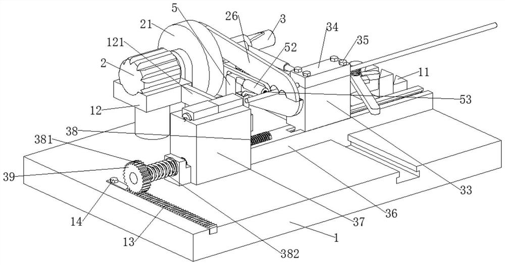
[0036] On the basis of the second embodiment, further, one end of the rectangular bar 36 away from the locking block 33 is slidably connected with a placing block 37 for placing the optical fiber plug, and the placing block 37 is provided with a groove for matching with the optical fiber plug. 36 is rotatably connected with a threaded rod 38, one end of the threaded rod 38 away from the rectangular strip 36 is coaxially and fixedly connected with a cylindrical rod 381, the cylindrical rod 381 is rotatably connected with a gear 39, and the mounting plate 1 is mounted with a tooth meshing with the gear 39. The rack 13, the rack 13 is threadedly connected with a second screw 14, the mounting plate 1 is provided with a threaded hole that cooperates with the second screw 14, the lower surface of the placing block 37 is provided with a threaded groove that cooperates with the threaded rod 38, and the cylindrical rod 381 is sleeved with a second torsion spring 382, ​​the two ends of t...


PUM


Abstract

The invention discloses a quick connector for optical fiber installation, and belongs to the field of optical fiber connection.The quick connector for optical fiber installation comprises an installation plate, a base is fixedly connected to the installation plate, a motor is fixedly connected to the base, a sliding block is fixedly connected to a transverse plate, and a sliding groove matched with the sliding block is formed in a disc; two clamping plates matched with each other are rotationally connected to the transverse plate, mounting columns are fixedly connected to the two clamping plates, a tension spring is fixedly connected between the two mounting columns, and the two expansion cams alternately abut against the two clamping plates; the ends, away from the expansion cam, of the two clamping plates are provided with two first semicircular holes matched with each other and two second semicircular holes matched with each other, and the ends, close to the second semicircular holes, of the two clamping plates are fixedly connected with wiping cotton. According to the invention, through cooperation of structures such as the disc and the clamping plate, an effect of automatically peeling an optical fiber is achieved.

Description

technical field [0001] The invention relates to the technical field of optical fiber connection, in particular to a quick connector for optical fiber installation. Background technique [0002] Optical fiber is a transmission medium. It can transmit data such as telephone calls or computer data like ordinary copper cables. The difference is that optical fibers transmit optical signals instead of electrical signals. Therefore, optical fibers have many unique advantages, such as: wide bandwidth, low loss, shielding electromagnetic radiation, light weight, security and privacy, and have been widely used in network transmission. However, due to the limited length of optical fibers, when When the length is not enough, it needs to be connected with another optical fiber to increase the length of the optical fiber. In this way, the traditional method is to connect the two butted optical fibers by fusion splicing, which is very inconvenient in operation, and the fusion splicing equi...

Claims


Application Information

Patent Timeline
IPC IPC(8): G02B6/245G02B6/25G02B6/36G02B6/38
CPCG02B6/245G02B6/25G02B6/3616G02B6/3898
Inventor 张文
Owner 安徽扬子实业有限公司
Why Eureka
Try Eureka