Reconfigurable logic device based on magnetic skyrmion
A magnetic skyrmion and logic device technology, applied in the field of logic gate circuits, can solve difficult logic operations and other problems
- Summary
- Abstract
- Description
- Claims
- Application Information
AI Technical Summary
Problems solved by technology
Method used
Image
Examples
Embodiment 1
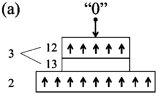
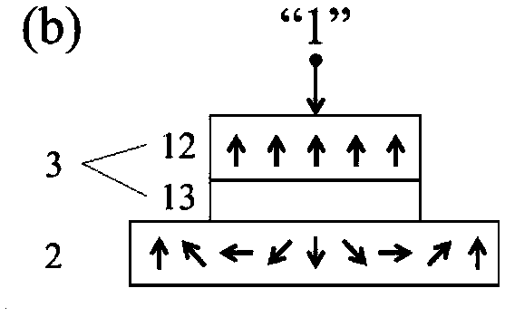
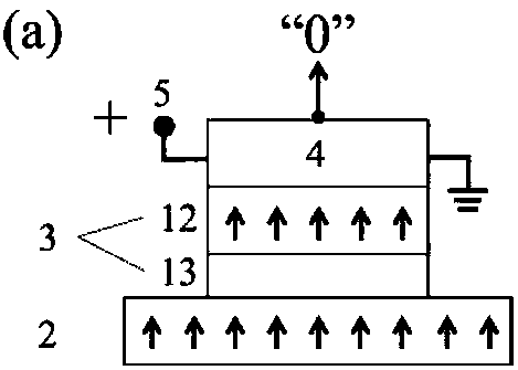
[0036] The logic device described in Embodiment 1 has a double-layer structure of a heavy metal layer 1 and a ferromagnetic layer 2; the ferromagnetic layer 2 is composed of two nanowire tracks placed in parallel and connected locally, one nanowire track is shorter than the other nanowire track, There are two connections between two parallel nanowire tracks, one is located at the right endpoint of the shorter nanowire track and the non-terminus of the longer nanowire track, and the other is located at the non-terminus of the two parallel nanowire tracks ; An MTJ is respectively placed at the left end of the two parallel nanowire tracks as input terminals 8 and 9, and an MTJ is placed at the other end of the longer nanowire track as output terminal 11; an antiferromagnetic layer 4 is arranged on each MTJ; at the output terminal An output control terminal 5 is set on the antiferromagnetic layer 4 of 11; a transmission control terminal 6 and 7 are respectively set on the two nanow...
Embodiment 2
[0050] The logic device described in Embodiment 2 has a double-layer structure of a heavy metal layer and a ferromagnetic layer; the ferromagnetic layer is composed of two nanowire tracks placed in parallel and partially connected, one nanowire track is shorter than the other nanowire track, and the two parallel nanowire tracks There is a connection between the nanowire tracks, which is located at the right end point of the shorter nanowire track and the non-end point of the longer nanowire track. The shorter nanowire track is located on the upper part of the ferromagnetic layer, and the entire ferromagnetic layer forms a supine " h" type; one MTJ is placed at the left end of the two parallel nanowire tracks as the input terminals 14 and 15, and one MTJ is placed at the other end of the longer nanowire track as the output terminal 16; there is an antiferromagnetic layer on each MTJ; An output control voltage is set on the antiferromagnetic layer of the output terminal 16; a pul...
Embodiment 3
[0055] The logic device described in Embodiment 3 has a double-layer structure of a heavy metal layer and a ferromagnetic layer; the ferromagnetic layer is composed of two nanowire tracks placed in parallel and partially connected, one nanowire track is shorter than the other nanowire track, and the two parallel nanowire tracks There is a connection between the nanowire tracks, which is located at the right end point of the shorter nanowire track and the non-end point of the longer nanowire track. The shorter nanowire track is located in the lower part of the ferromagnetic layer, and the entire ferromagnetic layer forms a "prone" h" type; one MTJ is placed at the left end of the two parallel nanowire tracks as the input terminals 17 and 18, and one MTJ is placed at the other end of the longer nanowire track as the output terminal 19; there is an antiferromagnetic layer on each MTJ; An output control voltage is set on the antiferromagnetic layer of the output terminal 19; a puls...
PUM
 Abstract
Description
Claims
Application Information
 - R&D
- Intellectual Property
- Life Sciences
- Materials
- Tech Scout
- Unparalleled Data Quality
- Higher Quality Content
- 60% Fewer Hallucinations
Browse by: Latest US Patents, China's latest patents, Technical Efficacy Thesaurus, Application Domain, Technology Topic, Popular Technical Reports.
© 2025 PatSnap. All rights reserved.Legal|Privacy policy|Modern Slavery Act Transparency Statement|Sitemap|About US| Contact US: help@patsnap.com


