Device for filling a can with a sliver

A technology for fiber strips and filling strips, which is applied in the direction of thin material handling, delivery of filamentous materials, transportation and packaging, etc., and can solve problems such as strip breakage and fiber strip drop

Active Publication Date: 2018-03-27
TRUETZSCHLER GRP SE
View PDF8 Cites 5 Cited by
  • Summary
  • Abstract
  • Description
  • Claims
  • Application Information

AI Technical Summary

Problems solved by technology

When the sliver is not guided perpendicularly to the roller axis, the sliver travels sideways and obliquely u...

Method used


Image

  • Device for filling a can with a sliver
  • Device for filling a can with a sliver
  • Device for filling a can with a sliver

Examples


Embodiment Construction

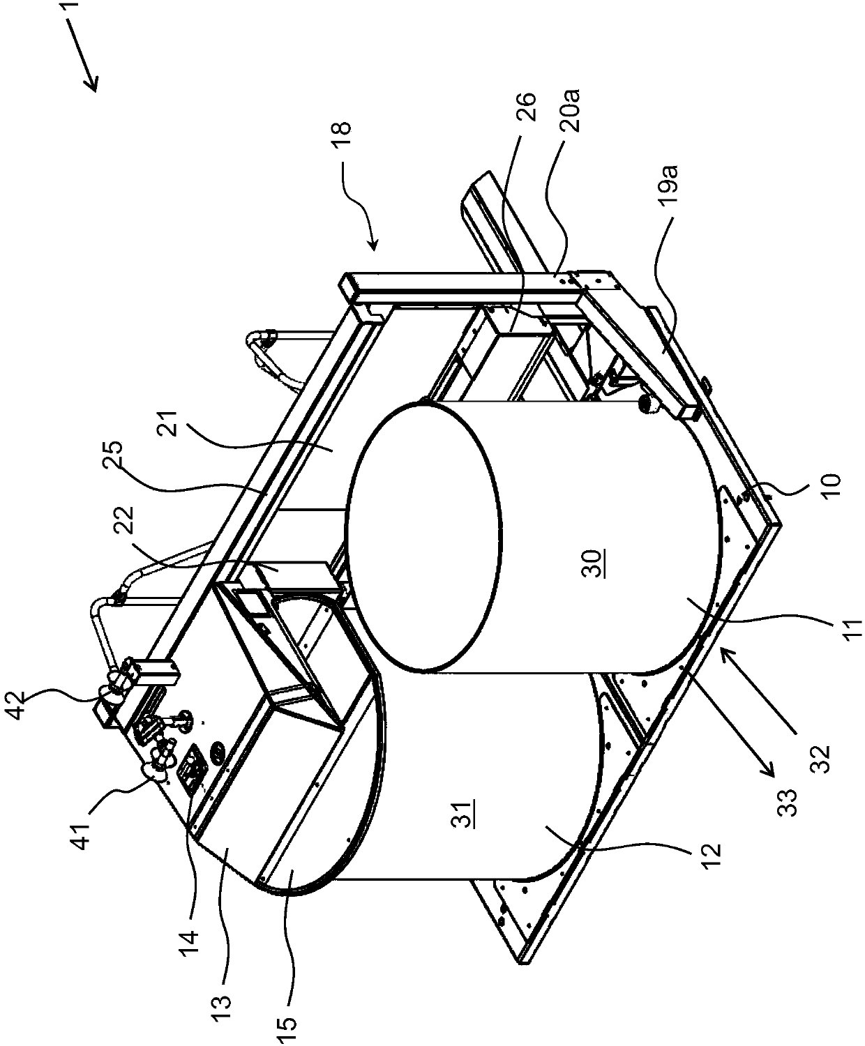
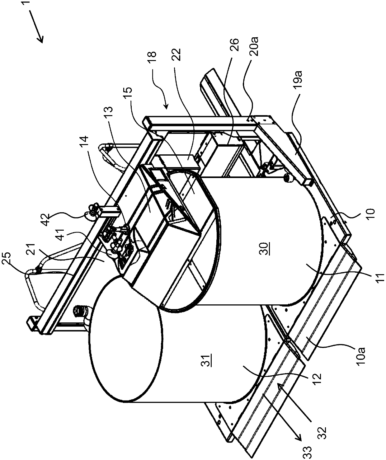
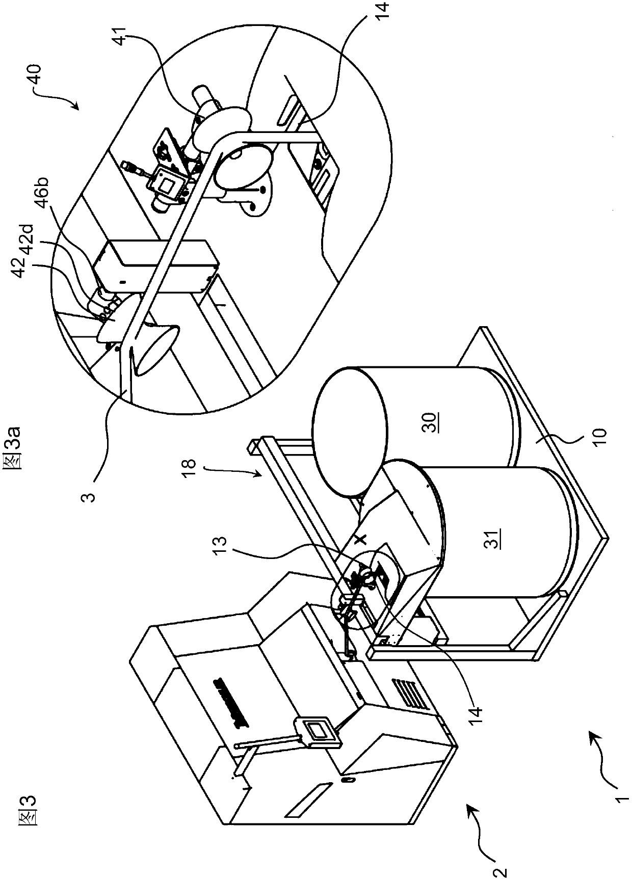
[0027] according to Figure 1 to Figure 2 The can changer 1 of the invention basically comprises a rectangular base plate 10 in which two can discs 11 , 12 are rotatably arranged. The base plate 10 serves as a rest or movement surface for cans which are moved or transported transversely to the longitudinal direction of the base plate 10 . The base plate 10 is substantially of a size or length suitable for receiving two cans side by side. exist figure 1 In the view of , a full or to-be-filled can 31 is shown on the left, and an empty can 30 is shown on the right. Each can 30 , 31 rests on its own rotatably driven can drum 11 , 12 , the drive of which is integrated in the base plate 10 . A coiling head 13 with an integrated turntable 14 is arranged above the full or to-be-filled can 31 . The fiber slivers, not shown, are guided, for example, from the card via guide rollers 41 and 42 to openings in the coiling head 13 and then to the turntable 14 , which rotates within the co...


PUM


Abstract

The present invention relates to a device for filling a can with a sliver produced in a spinning preparation installation, e.g. a drawing frame, carding machine or combing machine. The device is suitable to receive an empty and a full can at the same time, and comprises a depositing head (13) with a rotary plate (14). According to the invention, at least the rotary plate (14) is movably mounted, the device having at least one guide device (40) that can be adapted to the course of the sliver while the rotary plate (14) is moved.

Description

technical field [0001] The invention relates to an apparatus for filling cans with fiber sliver produced in a textile preparation facility such as a draw frame, card or comber, wherein the apparatus is adapted to accommodate both empty and full sliver drum, the device has a coil head with a turntable. Background technique [0002] In known prior art, the fiber sliver provided by the textile preparation machine is received by a so-called coiler. The fiber sliver is guided via the guide aid through the sliver bell to a pair of compaction rollers which deposit the fiber sliver via the turntable into the provided cans. If the can is full, the fiber strand is cut, wherein simultaneously the full can is removed and the empty can is replenished. When changing cans, there are linear or rotary can changers, which have different advantages depending on the shape and size of the cans and the space situation. Linear can changers are very compact in construction compared to rotary can...

Claims


Application Information

Patent Timeline
IPC IPC(8): B65H54/80B65H67/04B65H57/28
CPCB65H54/80B65H57/28B65H67/0434B65H2701/31
Inventor 克里斯托夫·莱德斯得克·拉夫莎
Owner TRUETZSCHLER GRP SE
Why Eureka
Try Eureka