Process for production of a screw for an extruder, and screw

A technology of extruders and screws, applied in the direction of presses, manufacturing tools, material forming presses, etc., can solve the problems of tungsten carbide being hard and impossible to achieve, and achieve the effect of reducing the risk of fracture

A technology of extruders and screws, applied in the direction of presses, manufacturing tools, material forming presses, etc., can solve the problems of tungsten carbide being hard and impossible to achieve, and achieve the effect of reducing the risk of fracture

CN101466523AInactive Publication Date: 2009-06-24THEYSOHN EXTRUSIONSTECHNIK GMBH

Image

  • Process for production of a screw for an extruder, and screw
  • Process for production of a screw for an extruder, and screw
  • Process for production of a screw for an extruder, and screw

Examples


Embodiment Construction

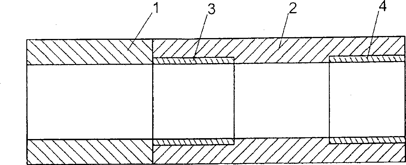
[0032] according to figure 1 The extruder housing comprises parts 1 and 2, which are connected to each other by flanges (not shown). Before the two parts 1 and 2 are connected to one another, a wear-resistant material is introduced into the two-sided part 2 . The wear-resistant material is figure 1 is represented by the insert 3 in the form of a sleeve.

[0033] The said screw should be coated in the region of the inserts 3 and 4 with a wear protection layer, for example with tungsten carbide, but in the remaining regions with a sliding layer, for example with molybdenum.

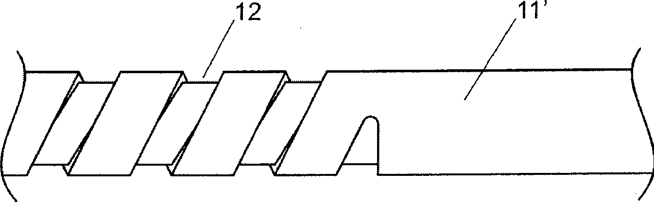
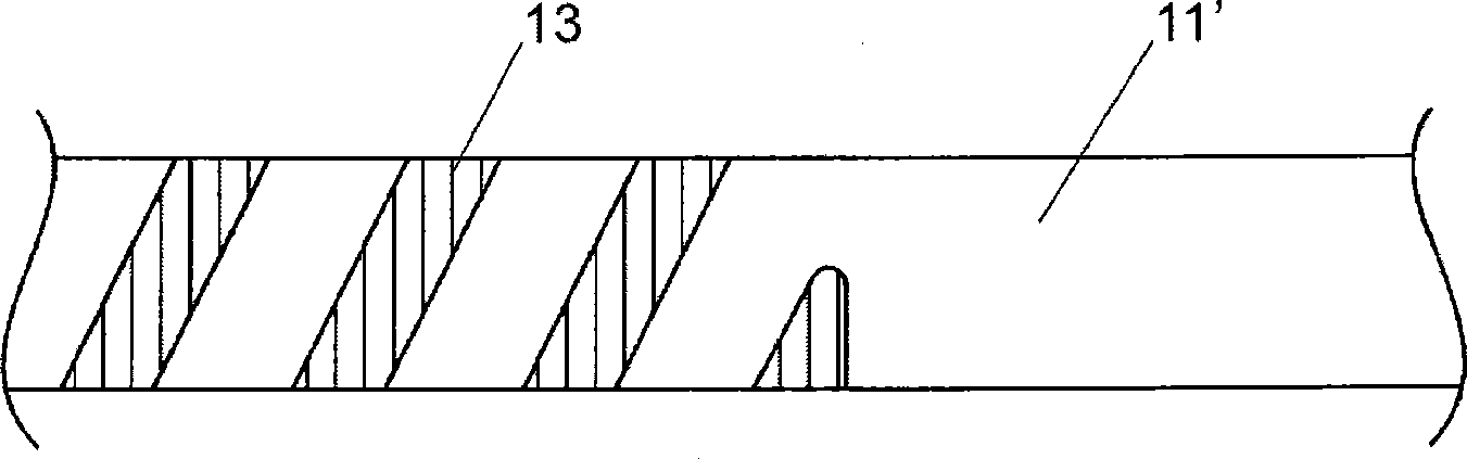
[0034] according to Figure 2 to Figure 6 The manufacturing process of such a screw is illustrated. The figures each show an axial region of the screw (or the base body of the screw) in which the transition from tungsten carbide to molybdenum is located (or should be located).

[0035] First, the bed 12 is milled out on the cylindrical base body 11' of the screw, specifically only in the region where t...


PUM

PropertyMeasurementUnit
lengthaaaaaaaaaa

Abstract

At least one section of the screw (11) has a wear-protection layer (13) and at least one other section of the screw preferably has an anti-friction layer (18). In a solid rod (11'), a bed (12) for the wear-protection layer (13) is first formed, and in this the wear-protection layer (13) is then applied, and finally the interstices (14) between the screw flights (15) are formed. According to the invention, the wear-protection layer (13), for example composed of tungsten carbide, is applied by build-up welding, and the interstices (14) are formed with lateral separation (16, 16') with respect to the wear-protection layer (13). For production of the anti-friction layer, the dimension of that / those section(s) of the screw (11) where the anti-friction layer, e.g. composed of molybdenum, is to be applied is reduced below specification, while providing lateral separation (19) with respect to the wear-protection layer. The anti-friction layer is then applied in the under-dimensioned region (17). Finally, the screw (11) is brought to the specified dimension.

Description

technical field [0001] The invention relates to a method for producing a screw for an extruder, wherein the screw is provided with a wear protection layer at least in one section, wherein first a base for the wear protection layer is formed in the complete shaft bed, the wear protection layer is then applied in the bed and finally an intermediate space is formed between the flight ribs. The invention also relates in particular to a method for producing a screw which is additionally provided with a sliding layer in at least one further section. Finally, the invention also relates to such a screw. Background technique [0002] From EP 1614502 A it is known to cover the housing of an extruder with a particularly wear-resistant material in areas subject to high wear. The region can be defined both axially and radially. According to EP1614502A, in a counter-running twin-screw extruder, in the radial direction, especially the zones corresponding to 10 o'clock and 2 o'clock are ...

Claims


Application Information

Patent Timeline
24 Jun 2009
Publication
CN101466523A
IPC
B29C47/60; B29C48/395; B29C48/59
CPC
B29C47/0844; B29C47/0019; B29C47/60; B29C47/6075; B30B11/246; B29C47/0845; B29C48/07; B29C48/507
Inventors
E·施纳布尔