Supercharge Your Innovation With Domain-Expert AI Agents!

Portable steel bar bending machine for construction site

A portable, bending machine technology, applied in the field of steel processing equipment, can solve the problems of difficult operation, high price, insufficient storage of bending steel bars, etc., and achieve the effects of convenient operation, good bending, and easy popularization and use.

Active Publication Date: 2019-04-23
六安长城钢结构有限公司
View PDF5 Cites 0 Cited by
  • Summary
  • Abstract
  • Description
  • Claims
  • Application Information

AI Technical Summary

Problems solved by technology

It is precisely because of the many advantages of steel that it is widely used in the current construction, transportation and ship industries. In modern buildings, steel bars are also added to concrete to increase the strength of building materials. As the inner frame of concrete pouring, such as the concrete main frame, it is necessary to bend the steel bars to make the internal main frame, which is convenient for pouring concrete. The bent steel bars are generally processed uniformly and then transported to the construction site in batches, but because the amount of steel bars is one Unquantified, so there is often insufficient storage of bent steel bars, so workers are required to bend them on-site. Manual bending is difficult, but the special steel bar bending device is expensive and easy to move, so it cannot adapt to on-site bending of steel bars. Therefore, a new technical means is needed to solve these problems. The present invention provides a bending device with a convenient structure, simple structure and easy operation, so that workers can better bend steel bars at the construction site.

Method used


Image

  • Portable steel bar bending machine for construction site
  • Portable steel bar bending machine for construction site
  • Portable steel bar bending machine for construction site

Examples


Embodiment approach

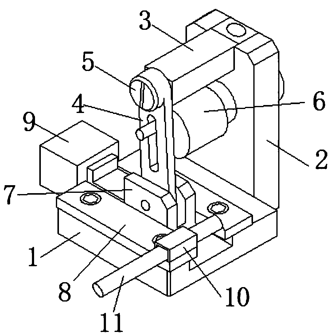
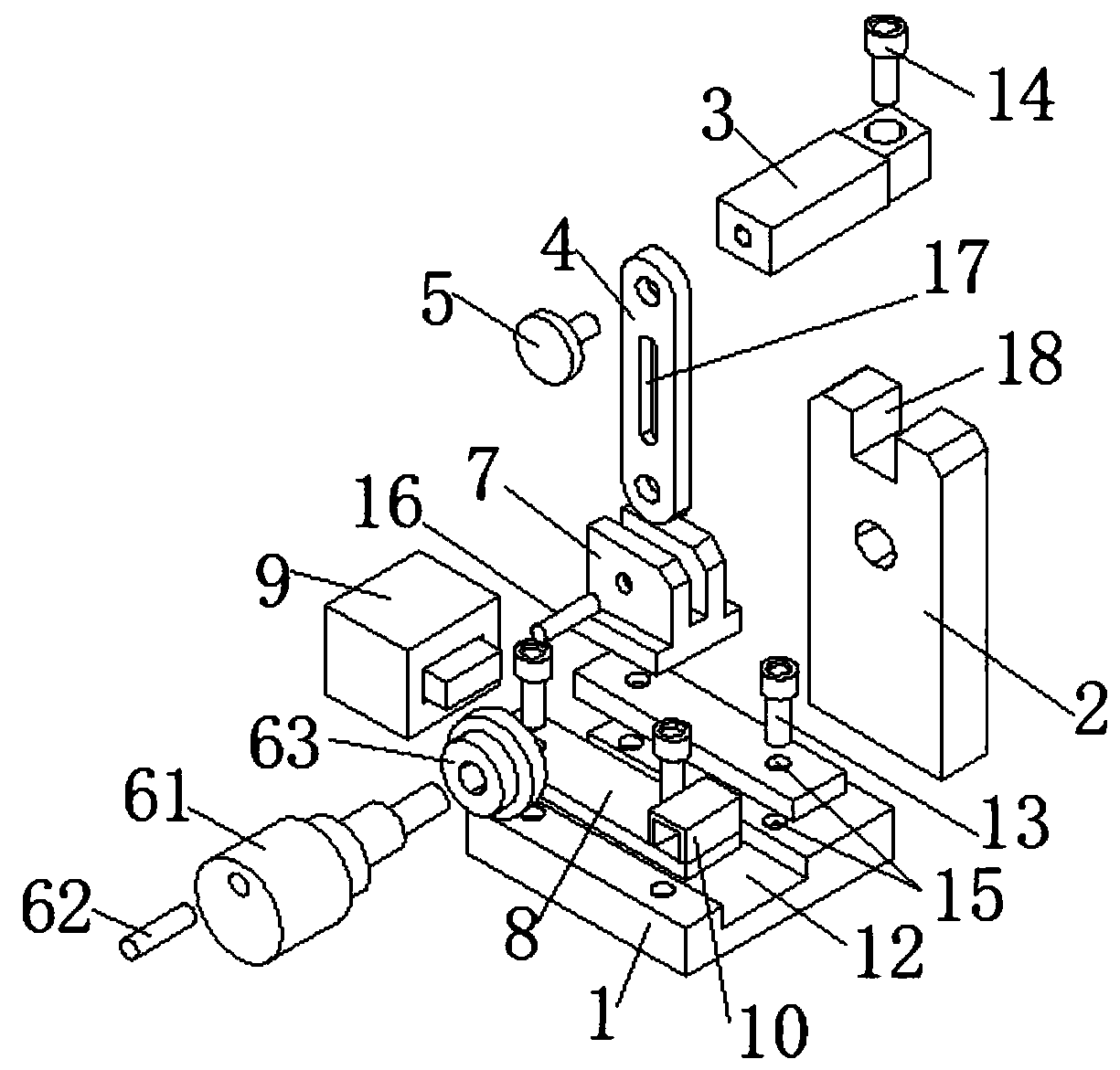
[0020] see figure 1 with figure 2 , the present invention provides the following embodiments: a portable steel bar bending machine for a construction site, including an underframe 1, a support platform 2, a hydraulic propulsion device 9 and a runner 6, and one side of the underframe 1 is fixedly provided with a support platform 2. The top of the supporting platform 2 is fixedly provided with a main beam 3 perpendicular to it, the other end of the main beam 3 is connected with one end of the rotating plate 4 through the rotating pin 5, and the other end of the rotating plate 4 is connected with the pusher arranged on the bottom frame 1. The table 7 is hingedly connected, the inside of the rotating plate 4 is connected with the runner 6 fixed on the support table 2, and a pressing plate 8 is fixed on the upper surface of the chassis 1, and the pressing plate 8 limits the pushing platform 7 to the chassis 1. One end surface of the push platform 7 is in contact with the telescop...


PUM


Abstract

The invention discloses a portable steel bar bending machine for the construction site. The portable steel bar bending machine comprises a bottom frame, a supporting table, a hydraulic propelling device and a rotation wheel. The supporting table is fixedly arranged on one side of the bottom frame, and a main beam perpendicular to the supporting table is fixedly arranged at the upper portion of thesupporting table. The other end of the main beam is rotationally connected with one end of a rotation plate through a rotation pin, and the other end of the rotation plate is connected with a pushingtable in a hinged manner, wherein the pushing table is arranged above the bottom frame. A pressing plate is fixedly arranged on the upper surface of the bottom frame. One end face of the pushing table makes contact with the telescopic end of the hydraulic propelling device fixed to the side face of the bottom frame, and a limiting hole groove is fixedly formed in the end, away from the hydraulicpropelling device, of the pressing plate. The portable steel bar bending machine is simple in structure and convenient to use, rapid bending work can be conducted on steel bars, and operation is convenient and fast; and the portable steel bar bending machine is simple in structure and low in manufacturing cost, and workers conveniently conduct operation on the construction site.

Description

technical field [0001] The invention belongs to the technical field of steel processing equipment, in particular to a portable steel bar bending machine for construction sites. Background technique [0002] Steel structure building is one of the main building types at present. Because steel has high strength, light weight, good overall rigidity and strong deformation ability, it is especially suitable for building long-span, super high and super heavy buildings; material homogeneity With good isotropy and isotropy, it is an ideal elastic body, which is most in line with the basic assumptions of general engineering mechanics; the material has good plasticity and toughness, can have large deformation, and can withstand dynamic loads well; the construction period is short; its high degree of industrialization can be Carry out specialized production with a high degree of mechanization. It is precisely because of the many advantages of steel that it is widely used in the current...

Claims


Application Information

Patent Timeline
Patent Type & Authority Patents(China)
IPC IPC(8): B21F1/00
CPCB21F1/00
Inventor 柳建新杜金龙
Owner 六安长城钢结构有限公司
Features
  • R&D
  • Intellectual Property
  • Life Sciences
  • Materials
  • Tech Scout
  • Unparalleled Data Quality
  • Higher Quality Content
  • 60% Fewer Hallucinations
Learn More