Drilling machining positioning component for engine crankshaft bearing cover

A technology for positioning components and crankshaft bearings, used in metal processing machinery parts, positioning devices, metal processing and other directions, can solve the problems of economic loss, inconvenient identification, quality accidents, etc., and achieve the effect of precise positioning

Pending Publication Date: 2018-03-30
盐城市精派组合机床有限公司
View PDF11 Cites 0 Cited by
  • Summary
  • Abstract
  • Description
  • Claims
  • Application Information

AI Technical Summary

Problems solved by technology

[0002] The existing crankshaft bearing cap needs to have a marking mechanism that can distinguish the correct assembly direction and facilitate correct assembly and number marking and necessary mounting holes. The above-mentioned marks or holes are generally placed on the top surface of the crankshaft bearing cap. The top surface of the crankshaft bearing cap is arc-shaped, which is inconvenient for processing on the one hand, and inconvenient to identify on the other hand, which will cause the slip groove to fail to connect when the bearing shell is assembled in the final assembly, resulting in irreversible serious quality accidents and economic losses ; Therefore, it is necessary to design the corresponding engine crankshaft bearing cap drilling and positioning assembly

Method used


Image

  • Drilling machining positioning component for engine crankshaft bearing cover
  • Drilling machining positioning component for engine crankshaft bearing cover

Examples


Embodiment Construction

[0011] Preferred embodiments of the present invention will be described in detail below in conjunction with the accompanying drawings;

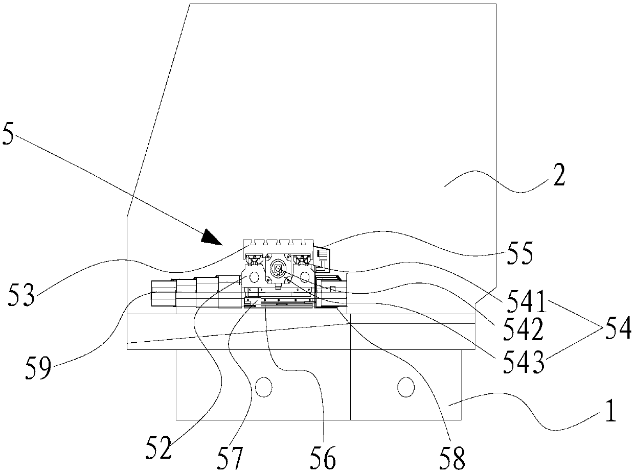
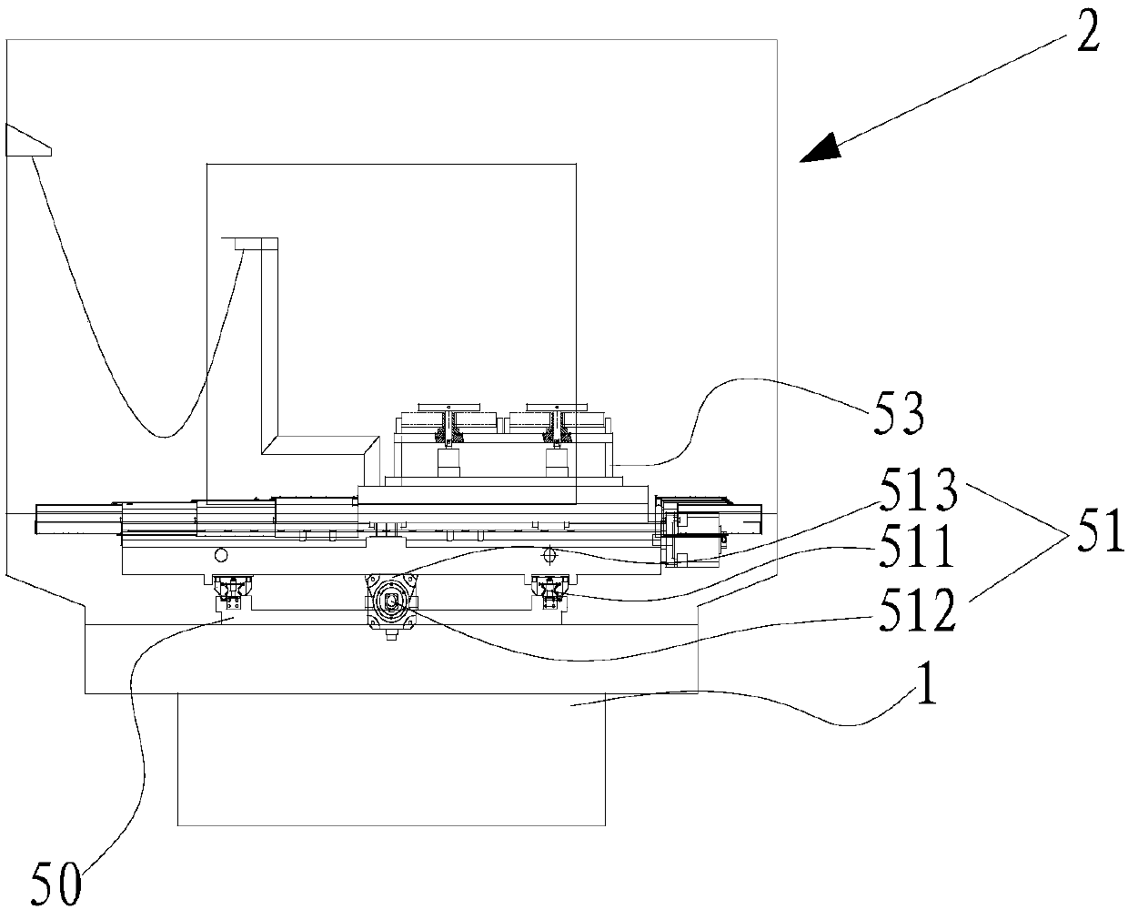
[0012] Such as figure 1 and figure 2 The shown engine crankshaft bearing cover drilling and positioning assembly 5 includes multiple supporting bases 50 fixed on the upper surface of the base 1 and arranged at intervals, a material receiving base 52 slidably installed on the supporting bases 50 , a slidable The bearing cover clamp 53 installed on the material receiving base 52, the material guide plate 55 installed on the side of the bearing cover clamp 53 (it can correspond to the support frame 2), the limit position fixed on the outer surface of the support bottom column 50 Slide rail 56 and be slidably installed on the limit slide rail 56 and the upper end extends to the support slide block 57 that is fixed on the bottom of material receiving base 52 (utilizing the cooperation of support slide block 57 and limit slide rail 56 can hold ma...


PUM


Abstract

The invention relates to a drilling machining positioning component for an engine crankshaft bearing cover. The drilling machining positioning component comprises multiple supporting bottom posts which are fixed on the upper surface of a base at intervals, a material bearing substrate which is slidably arranged on the supporting bottom posts, a bearing cover clamp which is slidably arranged on thematerial bearing substrate, a material guiding plate which is arranged on the side surface of the bearing cover clamp, limiting slide rails which are fixed on the outer side surfaces of the supporting bottom posts and supporting slide blocks which are slidably arranged on the limiting slide rails; the upper ends of the supporting slide blocks extend and are fixed on the bottom of the material bearing substrate; and the sliding direction of the bearing cover clamp on the material bearing substrate is vertical to the sliding direction of the material bearing substrate on the supporting bottom posts. Therefore, precise control of the bearing cover clamp in two directions can be realized; and the bearing cover clamp is precisely positioned and fixedly clamped.

Description

technical field [0001] The invention relates to a positioning assembly, in particular to an engine crankshaft bearing cover drilling processing positioning assembly. Background technique [0002] The existing crankshaft bearing cap needs to have a marking mechanism that can distinguish the correct assembly direction and facilitate correct assembly and number marking and necessary mounting holes. The above-mentioned marks or holes are generally placed on the top surface of the crankshaft bearing cap. The top surface of the crankshaft bearing cap is arc-shaped, which is inconvenient for processing on the one hand, and inconvenient to identify on the other hand, which will cause the slip groove to fail to connect when the bearing shell is assembled in the final assembly, resulting in irreversible serious quality accidents and economic losses ; Therefore, it is necessary to design the corresponding engine crankshaft bearing cap drilling and positioning assembly. Contents of th...

Claims


Application Information

Patent Timeline
Patent Type & Authority Applications(China)
IPC IPC(8): B23Q7/00B23Q3/06
CPCB23Q3/062B23Q7/00
Inventor 施志华
Owner 盐城市精派组合机床有限公司
Why Eureka
Try Eureka