Movable type positioning detection device

A positioning detection device and movable technology, applied in the direction of claw arms, manipulators, manufacturing tools, etc., can solve the problems of small detection range and waste of man-hours, and achieve the effects of convenient operation, flexible scanning mode and large detection range

Pending Publication Date: 2018-03-30
苏州弘瀚自动化科技有限公司
View PDF0 Cites 0 Cited by
  • Summary
  • Abstract
  • Description
  • Claims
  • Application Information

AI Technical Summary

Problems solved by technology

[0002] In the field of automatic processing, in order to make the production line run smoothly, it is necessary to perform positioning detection on the workpiece on the workbench. In the prior art, the detection camera is generally installed on the workbench to perform calibration detection on the workpiece. This method It can only detect the positioning of a fixed position, the detection range is small, and the mechanical arm in the production line needs to wait until it receives the signal of the completion of the positioning of the workpiece to start, thus wasting the man-hour from the start of the mechanical arm to the movement to the positioning point

Method used


Image

  • Movable type positioning detection device
  • Movable type positioning detection device

Examples


Embodiment Construction

[0012] The present invention will be further described below in conjunction with the accompanying drawings and specific embodiments, so that those skilled in the art can better understand the present invention and implement it, but the examples given are not intended to limit the present invention.

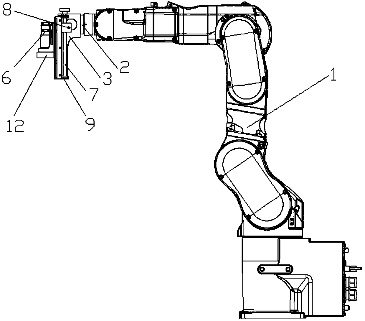
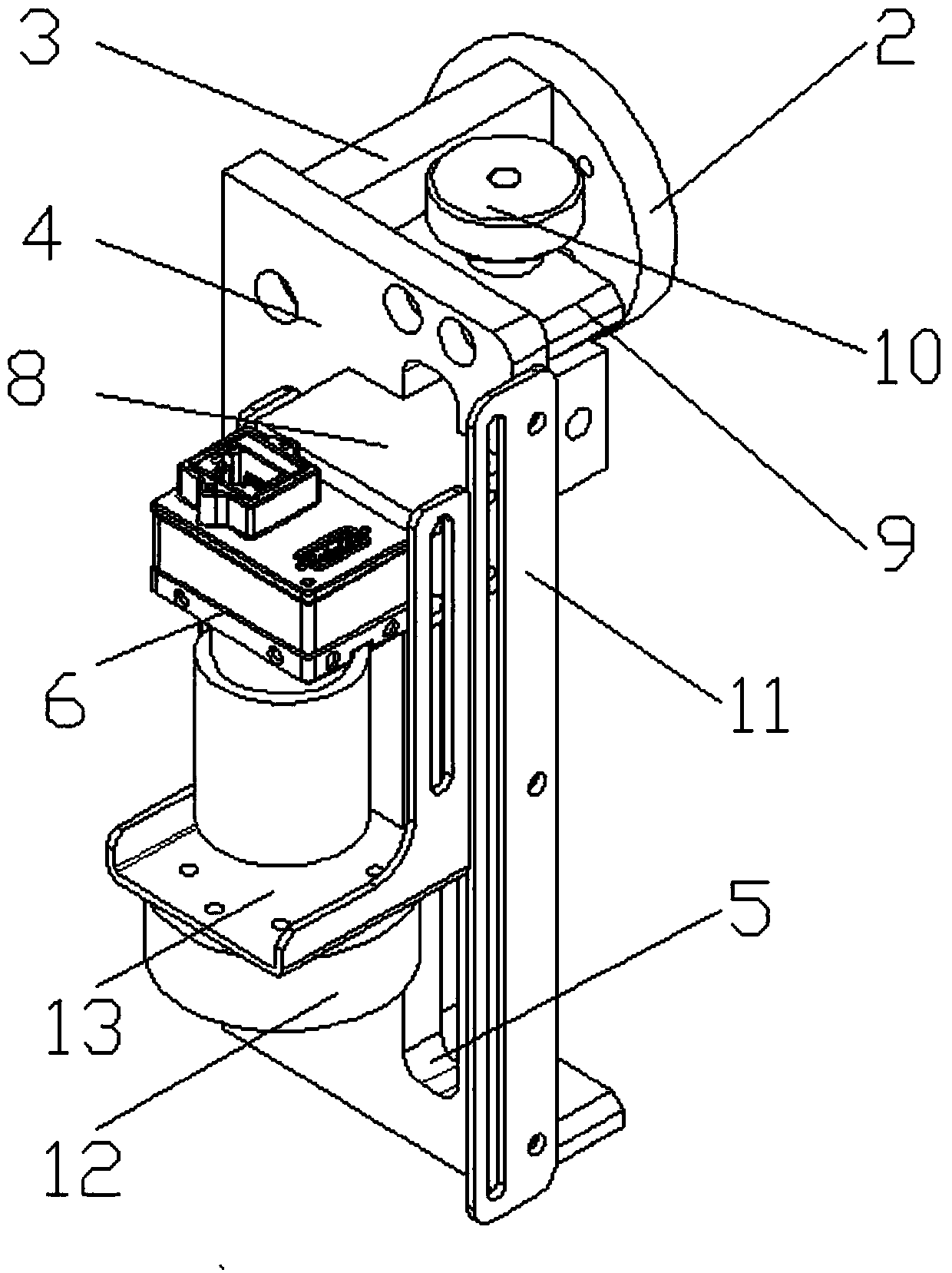
[0013] Such as figure 1 , figure 2 As shown, a movable positioning detection device includes a mechanical arm 1, a main board 3 perpendicular to the flange 2 is installed on the flange 2 of the mechanical arm 1, and the other side of the main board 3 opposite to the flange 2 is A vertical plate 4 parallel to the flange 2 is fixed, and a guide groove 5 parallel to the main board 3 in the longitudinal direction is provided on the vertical plate 4. The camera 6 is arranged on the opposite surface of the vertical plate 4 and the main board 3. The vertical plate 4 and the The contact side of the main board 3 is also provided with an adjustment screw 7, the fixed block 8 passes throug...


PUM


Abstract

The invention discloses a movable type positioning detection device. The movable type positioning detection device comprises a mechanical arm, wherein a main plate perpendicular to a flange plate is further mounted on the flange plate of the mechanical arm; a vertical plate parallel to the flange plate is fixed on the other side of the main plate; a guide groove parallel to the main plate is formed in the vertical plate; an adjustment screw is mounted on the vertical plate; the adjustment screw and the main plate are positioned on the same side of the vertical plate; each of the two ends of the adjustment screw is fixed on the vertical plate through an adjustment block; an adjustment wheel is further mounted at one end of the adjustment screw; a camera is arranged on the surface, back on to the main plate, of the vertical plate; a fixing block used for fixing the camera is connected with the adjustment screw after penetrating through the guide groove; and the mechanical arm drives a camera to scan a workpiece to carry out positioning detection, then the mechanical arm directly rotates to enable other parts picked by the mechanical arm to be mounted on a workpiece, and with the adoption of the method, the scanning detection range is wider and the working time is saved.

Description

technical field [0001] The invention relates to the field of automatic processing, in particular to a movable positioning detection device. Background technique [0002] In the field of automatic processing, in order to make the production line run smoothly, it is necessary to perform positioning detection on the workpiece on the workbench. In the prior art, the detection camera is generally installed on the workbench to perform calibration detection on the workpiece. This method It can only detect the positioning situation at a fixed position, and the detection range is small, and the mechanical arm in the production line needs to wait until it receives the signal that the workpiece positioning is completed before starting, thus wasting the man-hours from starting the mechanical arm to moving to the positioning point. Contents of the invention [0003] The technical problem to be solved by the present invention is to provide a positioning detection device that saves man-h...

Claims


Application Information

Patent Timeline
IPC IPC(8): B25J18/00
CPCB25J18/00
Inventor 陈信宏
Owner 苏州弘瀚自动化科技有限公司
Why Eureka
Try Eureka