Single-piston hydraulic oil cylinder

A technology of hydraulic oil cylinder and single piston, applied in the field of hydraulic oil cylinder, can solve the problems of incompatibility with industrialized large-scale production, poor use effect, unreasonable structural design, etc., and achieve the effects of high work efficiency, good use effect and reasonable structural design.

Inactive Publication Date: 2018-03-30
徐州昊圣机械制造有限公司
0 Cites 1 Cited by

AI-Extracted Technical Summary

Problems solved by technology

[0002] At present, the existing single-piston hydraulic cylinder has unreasonable s...

Abstract

The invention discloses a single-piston hydraulic oil cylinder, which comprises a rear cylinder cover (1), a first elastic washer (2), a piston sealing ring (3), a guide ring (4), a piston (5), a cylinder barrel (6 ), spring (7), second elastic washer (8), piston rod (9), front cylinder cover (10), nut (11), guide sleeve (12) and snap ring (13), the cylinder (6) The two ends are respectively connected to the front cylinder head (10) and the rear cylinder head (1) through the second elastic washer (8) and the first elastic washer (2), and the piston rod (9) runs through the cylinder ( 6), the outer side of the front cylinder head (10) is fixed with a guide sleeve (12) through a snap ring (13), the outer side of the guide sleeve is provided with a nut, the piston rod is provided with a spring member, and the piston A piston is arranged at one end of the rod, and the piston is connected with a guide ring through a piston sealing ring, and an oil inlet hole (14) is arranged on the rear cylinder cover. The invention adopts a single-piston hydraulic oil cylinder, and the structure design is reasonable.

Application Domain

Fluid-pressure actuators

Technology Topic

EngineeringMechanical engineering +4

Image

  • Single-piston hydraulic oil cylinder

Examples

  • Experimental program(1)

Example Embodiment

[0010] The present invention will be further explained below in conjunction with the accompanying drawings and embodiments.
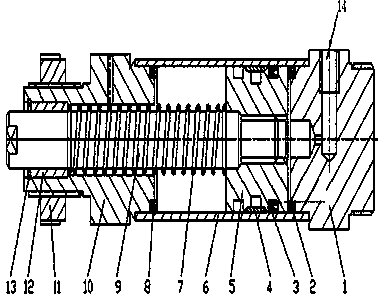
[0011] like figure 1 As shown, a single-piston hydraulic oil cylinder includes a rear cylinder cover 1, a first elastic washer 2, a piston sealing ring 3, a guide ring 4, a piston 5, a cylinder barrel 6, a spring member 7, a second elastic washer 8, a piston Rod 9, front cylinder cover 10, nut 11, guide sleeve 12 and snap ring 13, the two ends of the cylinder 6 are respectively connected with the front cylinder cover 10 and the rear cylinder cover 1 through the second elastic washer 8 and the first elastic washer 2 , the piston rod 9 runs through the cylinder 6, the outer side of the front cylinder head 10 is fixed with a guide sleeve 12 through a snap ring 13, the outer side of the guide sleeve 12 is provided with a nut 11, and the piston rod 9 is provided with A spring member 7, a piston 5 is provided at one end of the piston rod 9, and the piston 5 is connected with the guide ring 4 through the piston sealing ring 3, and an oil inlet hole 14 is provided on the rear cylinder head 1.
[0012] The spring element 7 is made of high elastic material. Both the first elastic washer 2 and the second elastic washer 8 are O-shaped elastic washers.
[0013] The above content is an example and description of the present invention, but it does not mean that the advantages that the present invention can obtain are limited by this, and any simple transformation of the structure that may be possible in the practice of the present invention, and/or one of the advantages realized in some embodiments or more are within the protection scope of the present application.

PUM

no PUM

Description & Claims & Application Information

We can also present the details of the Description, Claims and Application information to help users get a comprehensive understanding of the technical details of the patent, such as background art, summary of invention, brief description of drawings, description of embodiments, and other original content. On the other hand, users can also determine the specific scope of protection of the technology through the list of claims; as well as understand the changes in the life cycle of the technology with the presentation of the patent timeline. Login to view more.

Similar technology patents

Long-rubber-barrel differential pressure type water filling packer capable of washing well

Owner:DRILLING TECH DEV CO LTD OF TIANJIN DAGANG OILFIELD PETROLEUM ENG INST +1

Classification and recommendation of technical efficacy words

  • Reasonable structural design
  • Improve work efficiency

Cooperation service platform facing different source data

InactiveCN101174957AImprove management level and qualityImprove work efficiency
Owner:NANJING UNIV OF FINANCE & ECONOMICS

Screw drilling tool, vertical drilling tool testing method and well inclination simulation testing equipment

InactiveCN111594144AReduced height requirementsImprove work efficiency
Owner:DEZHOU UNITED GASOLINEEUM MACHINERY

Method for intelligent automatic identification of transmission circuit parts

Owner:INFORMATION COMM COMPANY STATE GRID SHANDONG ELECTRIC POWER +2

Keyboard spill-proofing mechanism

ActiveUS7030330B2minimize manufacturing costimprove work efficiency
Owner:LITE ON SINGAPORE PTE LTD
Why Eureka
Try Eureka