Stoking machine

A technology of furnace smelting machine and walking mechanism, which is applied to furnaces, furnace components, descaling devices, etc., can solve the problems of small working range of smelting furnaces, and achieve the effect of increasing the working range and running smoothly

Pending Publication Date: 2018-03-30
张耀庭
View PDF5 Cites 0 Cited by
  • Summary
  • Abstract
  • Description
  • Claims
  • Application Information

AI Technical Summary

Problems solved by technology

The main problem of the current smelting machine is that the rail trolley and the telescopic oil cylinder run in a straight line, so the working range of the smelting machine is small, and it is usually necessary to configure multiple smelting machines to adapt to the smelting operation at each position

Method used


Image

  • Stoking machine
  • Stoking machine
  • Stoking machine

Examples


Embodiment Construction

[0023] In order to make the technical problems, technical solutions and advantages to be solved by the present invention clearer, the following will describe in detail with reference to the drawings and specific embodiments.

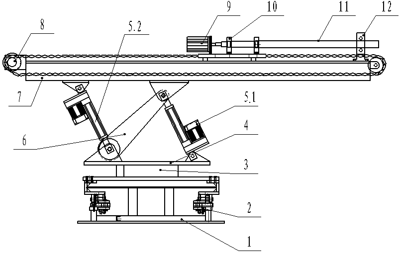
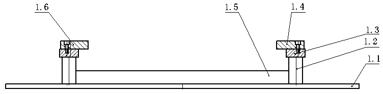
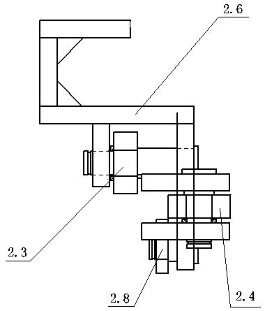
[0024] Such as figure 1 As shown, a furnace stamping machine includes a guide rail 1, a traveling mechanism 2, a turntable drive 3, a rotating platform 4, an electric push rod 5, a support arm 6, an upper workbench 7, a drill rod motor 9, a bearing seat 10, a drill rod 11 and the drill pipe support seat 12, the traveling mechanism 2 is arranged on the guide rail 1, the traveling mechanism 2 is provided with a rotating platform 4, the rotating platform 4 is controlled by the turntable drive 3, and the upper side of the rotating platform 4 is hinged with one end of the supporting arm 6, supporting The other end of the arm 6 is hinged with the bottom of the upper worktable 7, and the hinge of the support arm 6 and the rotating platform 4 is hinged with an e...


PUM


Abstract

The invention belongs to the technical field of metal metallurgical equipment, and particularly relates to a stoking machine. A running mechanism is mounted on a guide rail and provided with a rotating platform. The rotating platform is controlled by a rotating disc drive. The upper side of the rotating platform and one end of a supporting arm are hinged. The other end of the supporting arm and the bottom of an upper work table are hinged. An electric push rod I is hinged to the hinged portion of the supporting arm and the rotating platform at the same time. The other end of the electric pushrod I and the bottom of the upper work table are hinged. An electric push rod II is hinged to the hinged portion of the supporting arm and the upper work table at the same time. The other end of the electric push rod II and the rotating platform are hinged. A drilling machine movement platform capable of moving front and back along the upper work table is arranged on the upper work table. A drilling rod motor is fixed to the drilling machine movement platform and is connected with a drilling rod. One end of the drilling rod is fixed to bearing pedestals, and the other end of the drilling rod is arranged on a drilling rod supporting seat. According to the stoking machine, in the stoking process, a whole device operates on the guide rail stably, and stoking can be finely adjusted.

Description

technical field [0001] The invention belongs to the technical field of metallurgical equipment, in particular to a furnace stamping machine. Background technique [0002] In the smelting process of the submerged arc furnace, it is necessary to smash the agglomeration of the furnace material, etc., and the traditional method is mainly manual. However, during the smelting process, the working environment near the submerged arc furnace is relatively harsh, and manual work is inefficient and dangerous. Therefore, a furnace smelting machine was developed for furnace smelting operations. The function of the pounding machine is not only to feed materials, but also to use replaceable tools to make the distribution of materials in the electric furnace even, to expand the reaction area, to eliminate suspended materials, to crush slag, to reduce crusts and flames on the material surface, and to achieve smooth furnace conditions. . The main problem of the current furnace smelters is t...

Claims


Application Information

Patent Timeline
Patent Type & Authority Applications(China)
IPC IPC(8): F27D25/00
CPCF27D25/001
Inventor 张耀庭郭向东郭计虎芦晓燕张玉生刘志坚纪泽
Owner 张耀庭
Why Eureka
Try Eureka