
One-finger angular pneumatic gripper and respective manufacturing method

A technology of pneumatic clamps and jigs, which is used in the manufacture of tools, chucks, workpiece clamping devices, etc., can solve problems such as fracture and loss of pneumatic sealing, and achieve the effect of maximizing performance

Active Publication Date: 2018-04-03
GIMATIC SRL
View PDF8 Cites 0 Cited by
  • Summary
  • Abstract
  • Description
  • Claims
  • Application Information

AI Technical Summary

Problems solved by technology

Clamps must withstand millions of operating cycles, sometimes fractures occur at the ring nuts, such as the threads connecting them to the clamp body, and the pneumatic seal is lost

Method used


Image

  • One-finger angular pneumatic gripper and respective manufacturing method
  • One-finger angular pneumatic gripper and respective manufacturing method
  • One-finger angular pneumatic gripper and respective manufacturing method

Examples


Embodiment Construction

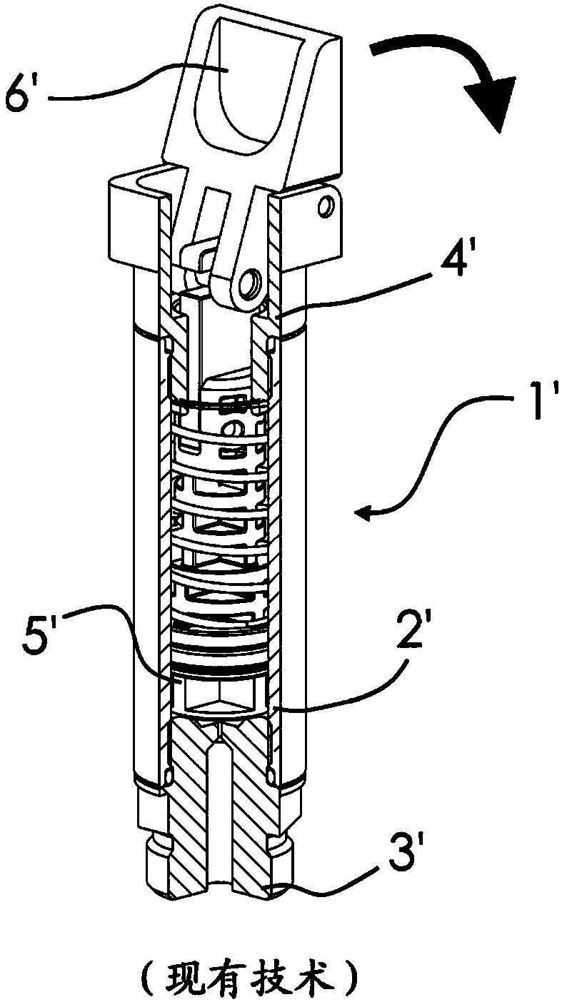
[0031] figure 1 A single-finger pneumatic gripper 1' according to known technology is shown. As mentioned above, this clamp 1' comprises a main body 2' which is generally an aluminum tube 2' with threaded ends. These ends are closed by respective plastic ring nuts 3' and 4' threaded to the body 2' of the clamp. The duct runs through the first ring nut 3', allowing compressed air to enter the body 2', said first ring nut 3' being figure 1 One of the lower ring nuts. A piston 5' is slidingly inserted into the body 2' to define a cylinder-piston coupling. Single clamping finger 6' hinged to second ring nut 4'— figure 1 the upper one of the ring nuts—and is connected to the piston in such a way that, according to the direction indicated by the arrow, the drive clamping finger is figure 1 Rotation between an open position shown and a closed position not shown.

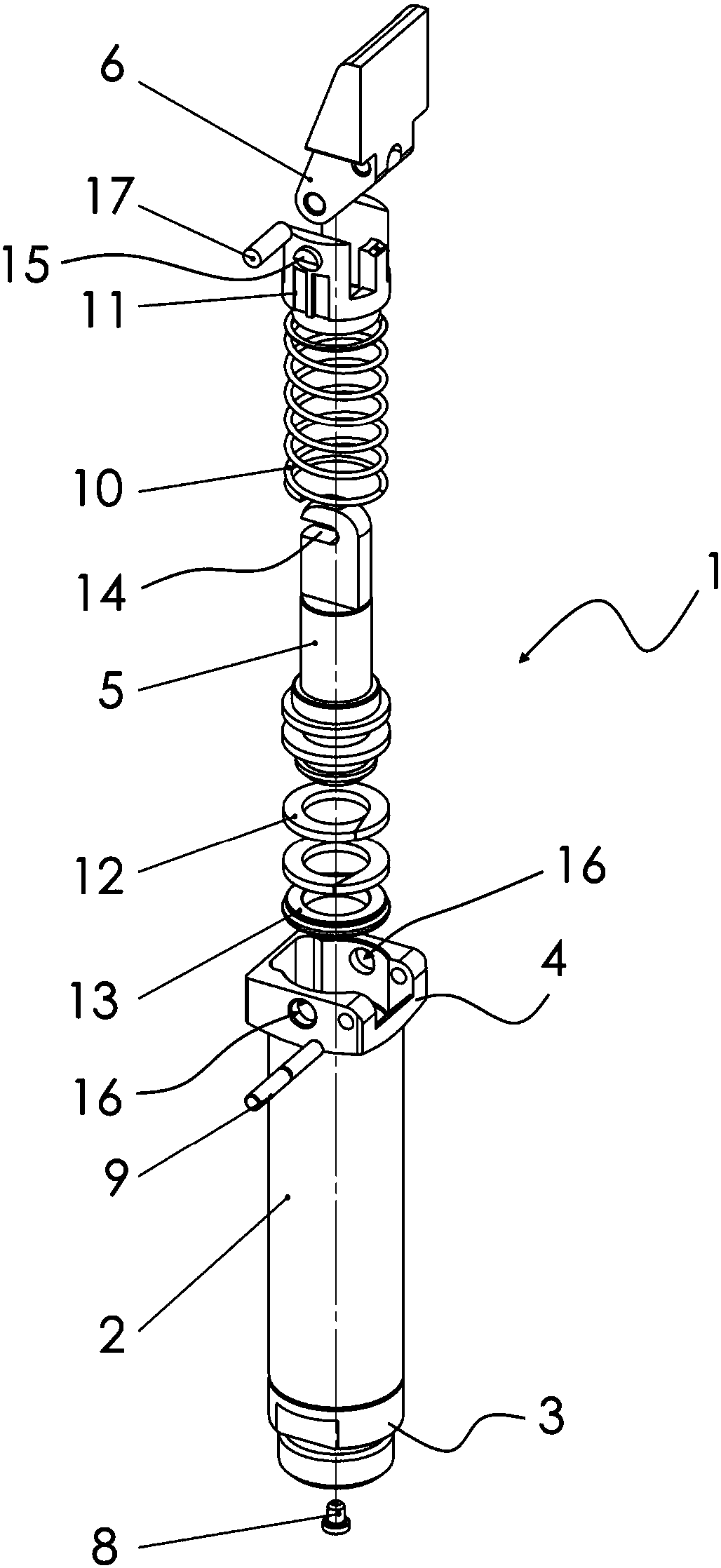
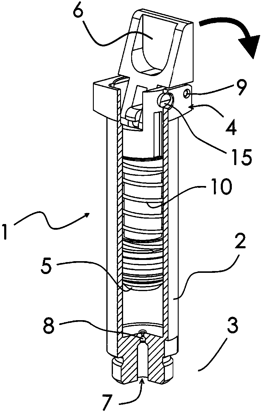
[0032] figure 2 An embodiment of a clamp 1 according to the invention is shown. Unlike the solutions according t...


PUM


Abstract

The invention discloses a one-finger angular pneumatic gripper including a body, in which a piston and a spring are accommodated, and a clamping finger hinged to the body. Differently from conventional solutions, the ends of the gripper body are not screwed or assembled ring nuts, but on the contrary they are integral parts of the body itself.

Description

technical field [0001] The invention relates to a single-finger angle pneumatic clamp and a manufacturing method thereof. Background technique [0002] In the field of industrial automation, it is known to use single-finger pneumatic grippers, such as those shown by the applicant in 2015, which are accessible via the Internet at the following page: http: / / www.gimatic.com / Gimatic / ProductsFiles / Catalogs / it / of.pdf. [0003] These are known as angle clamps because they are provided with a single jaw—hereafter referred to as the “grip finger”—that can be positioned in a vertical open position aligned with the clamp body itself and in an angled or transverse horizontal position relative to the clamp body. Rotate between closed positions. In fact, in the closed position, the clamping fingers project cantilevered from the clamp body. [0004] Movement of the gripping fingers is imparted by a pneumatic piston moving in the gripper body, so the gripper body acts as an air cylinder...

Claims


Application Information

Patent Timeline
Patent Type & Authority Applications(China)
IPC IPC(8): B25B11/00
CPCB25B11/00B25J15/022B25J15/12
Inventor G·贝兰迪
Owner GIMATIC SRL
Features
  • Generate Ideas
  • Intellectual Property
  • Life Sciences
  • Materials
  • Tech Scout
  • Unparalleled Data Quality
  • Higher Quality Content
  • 60% Fewer Hallucinations
Learn More