Eureka AIR delivers breakthrough ideas for toughest innovation challenges, trusted by R&D personnel around the world.

Method for operating a motor vehicle hydraulic brake system and hydraulic brake system for motor vehicle

A technology for hydraulic braking and motor vehicles, which is applied in the direction of braking action starting devices, braking transmission devices, brakes, etc., and can solve the pressure drop of the main brake cylinder, incorrect estimation of negative pressure, and unfavorable functions of hydraulic brake booster operation Impact and other issues

Inactive Publication Date: 2018-04-03
FORD GLOBAL TECH LLC
View PDF4 Cites 0 Cited by
  • Summary
  • Abstract
  • Description
  • Claims
  • Application Information

AI Technical Summary

Problems solved by technology

[0009] In the known methods for estimating the prevailing negative pressure in the brake booster, inaccuracies in particular may occur due to the fact that when hydraulic brake boosting operation is activated, that is, when hydraulic brake boosting operation is activated When activated, the measured brake pressure in the master brake cylinder does not lead to any definite conclusions about the stroke of the diaphragm in the brake booster
In addition, when hydraulic brake boosting operation is activated, even if the wheel brake pressure acting on the wheel brake device increases and the brake pedal is not released but continues to be depressed by the driver, the pressure in the master brake cylinder A drop in pressure may also occur
In known methods, the pressure drop in the brake master cylinder can be evaluated similarly to the release of the brake pedal, which leads to an incorrect estimation of the consumption of the vacuum and thus to an inaccuracy of the prevailing vacuum. correct estimate
Incorrect estimation of negative pressure or negative pressure reserve can adversely affect the function of the hydraulic brake booster operation

Method used


Image

  • Method for operating a motor vehicle hydraulic brake system and hydraulic brake system for motor vehicle

Examples


Embodiment Construction

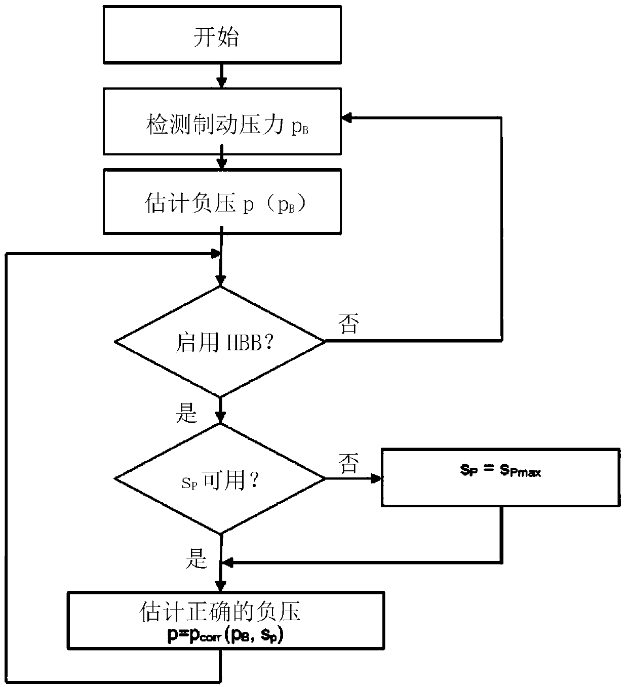
[0029] In the text below, driving situations in which the method according to the invention can be advantageously used are described as examples.

[0030] When the motor vehicle is running, the driver activates the brake pedal and the pedal force exerted by him continues to increase, with the result that the absolute atmospheric pressure in the working chamber is increased by changing the position of the valve in the brake booster. This slightly reduces the negative pressure prevailing in the negative pressure chamber, ie the absolute pressure in the negative pressure chamber increases slightly, as the volume of the chamber shrinks due to the movement of the diaphragm, while the number of air molecules initially remains the same.

[0031] If the increased brake pressure exceeds the corresponding threshold, the HBB function is activated. In this case, the brake fluid pump of the vehicle dynamics control system pumps brake fluid from the master brake cylinder to the wheel brake ...


PUM


Abstract

A method for operating a hydraulic brake system of a motor vehicle having a brake booster and a hydraulic brake boost wherein a brake pressure pB is detected and an underpressure p, prevailing in an underpressure chamber of the brake booster is estimated on the basis of the detected brake pressure pB. The hydraulic brake boost controlled based on the estimated underpressure p, with the estimated underpressure taking into account an actuation of the hydraulic brake boost. The invention further relates to a hydraulic brake system corresponding to the motor vehicle.

Description

technical field [0001] The invention relates to a method for operating a hydraulic brake system of a motor vehicle and to a hydraulic brake system for a motor vehicle. Background technique [0002] Today, braking systems of motor vehicles are often embodied as hydraulic braking systems. In such a braking system, a master brake cylinder is provided in which, by activating a piston connected to the brake pedal in a pressure chamber filled with brake fluid; pressure. The wheel brake apparatus includes a wheel cylinder that moves a brake caliper with brake pads mounted thereon against a brake drum or a brake disc based on the pressure of a brake fluid. In this way, the braking force acting on the wheels connected to the brake drum or disc can be generated and metered by activating the brake pedal. The master brake cylinder is usually embodied as a tandem master brake cylinder with two pressure chambers arranged next to each other, which are separated by a second piston and se...

Claims


Application Information

Patent Timeline
Patent Type & Authority Applications(China)
IPC IPC(8): B60T8/172B60T13/66
CPCB60T8/172B60T13/662B60T8/442B60T13/46B60T7/042B60T8/171B60T8/441B60T13/166
Inventor 伊恩·穆尔克里斯蒂安·席玛勒马蒂亚斯·鲍曼托马斯·斯文森
Owner FORD GLOBAL TECH LLC
Why Eureka
Eureka Blog
Learn More