Supercharge Your Innovation With Domain-Expert AI Agents!

Medicine dispensing mechanism

A technology for dispensing medicines and medicine boards, which is applied to conveyors, storage devices, transportation and packaging, etc. It can solve the problems of medicine jams, heavy weight, and complex statistics of medicines, so as to reduce friction, avoid medicine jams, and replace convenient effect

Pending Publication Date: 2018-04-03
韦乐海茨(上海)医药设备科技有限公司
View PDF0 Cites 0 Cited by
  • Summary
  • Abstract
  • Description
  • Claims
  • Application Information

AI Technical Summary

Problems solved by technology

[0003] In the existing design, the medicine dispensing module is generally installed on the medicine dispensing track of the medicine dispensing machine to realize the controllability of medicine dispensing, but the traditional medicine dispensing track generally adopts a continuous roller device, and the medicine box moves on the roller. Among them, the friction force is relatively large, and a large inclination angle needs to be adopted. Generally, the inclination angle of the drug delivery track is more than 28°, so that the medicine box can slide smoothly, and the traditional drug delivery track is generally made of stainless steel, and the weight heavier
And the traditional dispensing module is usually provided with a stopper, when the stopper protrudes from the surface of the dispensing track, it prevents the medicine box from sending out, and when the stopper sinks under the surface of the dispensing track, the medicine box can be released from the dispensing track. It often occurs that multiple boxes of medicines are sent out within an interval period, which makes the statistics of the number of medicines distributed complicated and exacerbates the uncontrollability of the medicines distribution process. When the stopper does not work normally, it will drug card phenomenon

Method used


Image

  • Medicine dispensing mechanism
  • Medicine dispensing mechanism
  • Medicine dispensing mechanism

Examples


Embodiment Construction

[0030] In order to enable those skilled in the art to better understand the technical solution of the present invention, its specific implementation will be described in detail below in conjunction with the accompanying drawings:

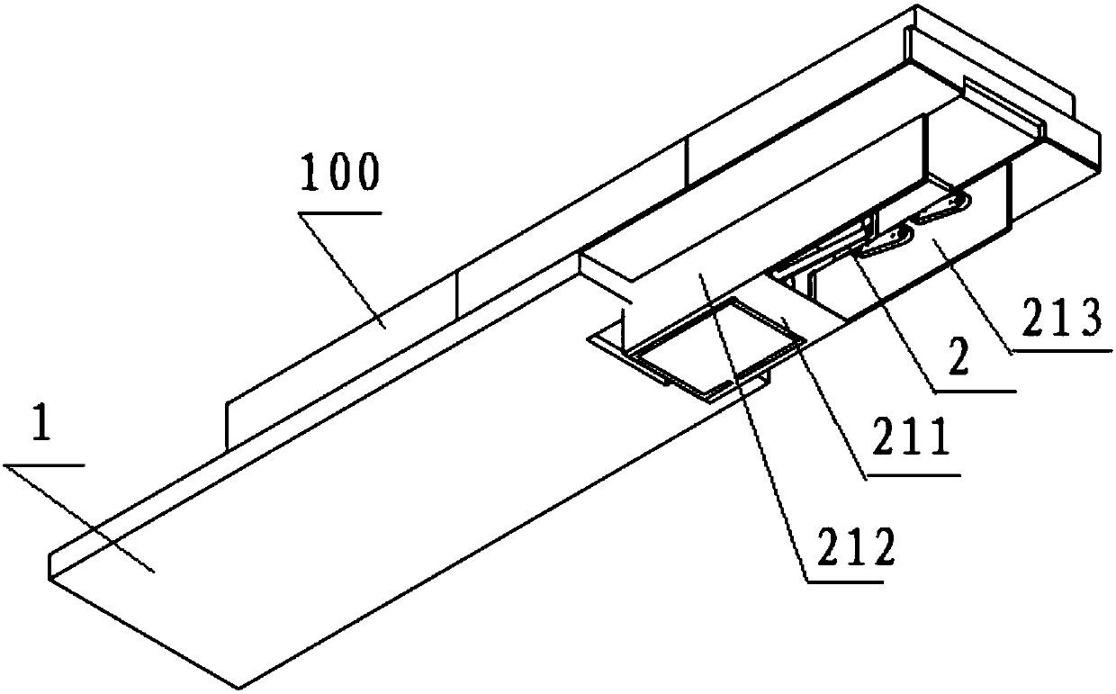
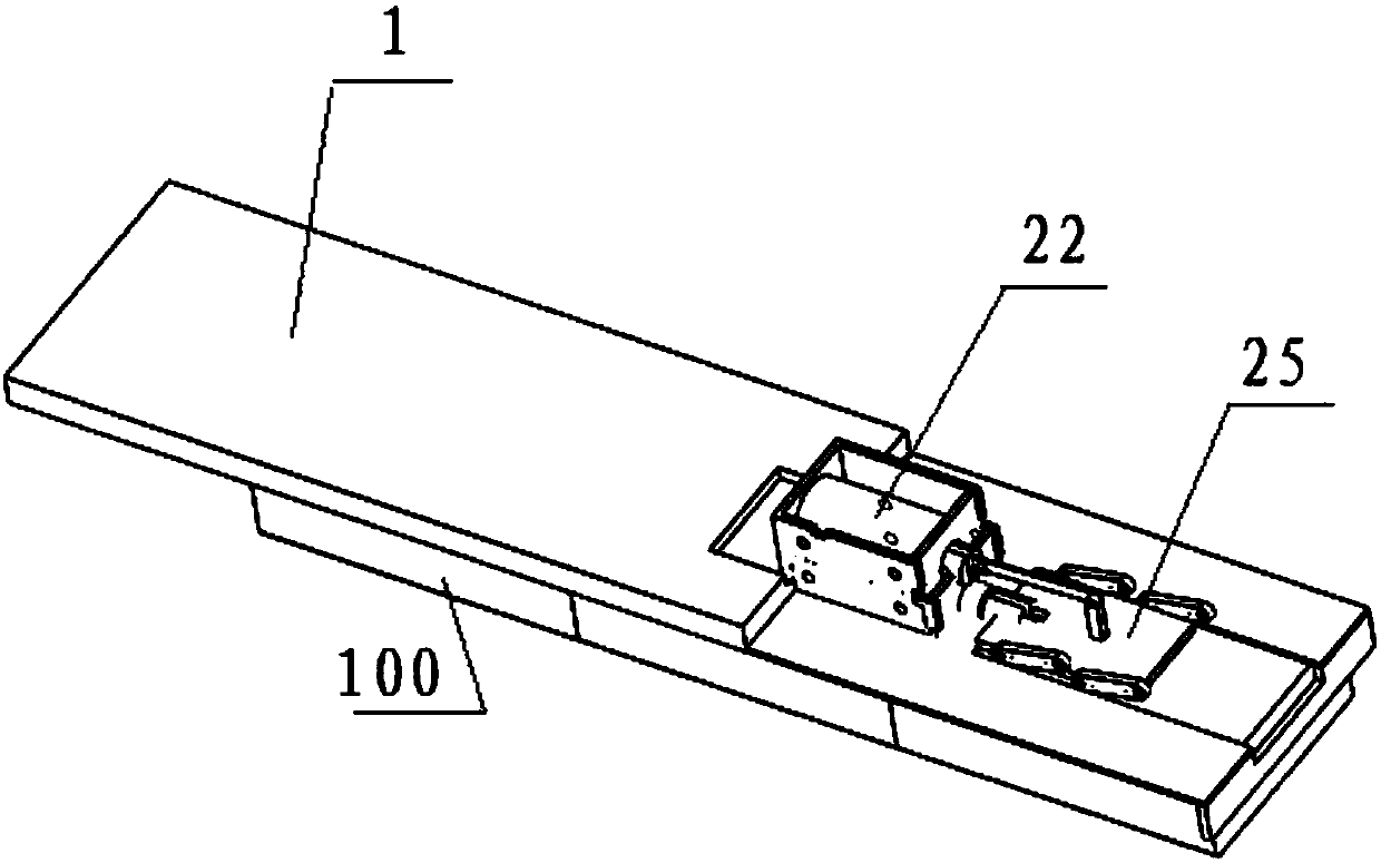
[0031] see Figures 1 to 5e , an embodiment of the present invention, a medicine dispensing mechanism, including a medicine dispensing laminate 1 and a medicine dispensing module 2 .

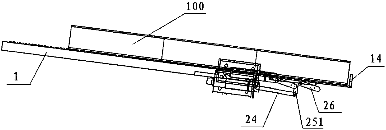
[0032] see again Figure 4a and Figure 4b The drug distribution laminate 1 includes a left aluminum frame 11, a right aluminum frame 12 and a plastic laminate 13, the left aluminum frame 11 and the right aluminum frame 12 are arranged oppositely, and the plastic laminate 13 is embedded in the left aluminum frame 11 and the right aluminum frame 12. Between the aluminum frame 12 on the right side, the front end of the plastic laminate 13 is provided with a drug blocking plate 14; The inclination angle of the plate 1 can be set to 15°. The plastic laminate 13 is mad...


PUM


Abstract

The invention discloses a medicine dispensing mechanism which comprises a medicine dispensing laminated plate and a medicine dispensing module. The medicine dispensing laminated plate comprises a left-side aluminum frame, a right-side aluminum frame and a plastic laminated plate body. The left-side aluminum frame and the right-side aluminum frame are arranged oppositely, the plastic laminated plate body is embedded between the left-side aluminum frame and the right-side aluminum frame, and the front end of the plastic laminated plate body is provided with a medicine baffle plate. The medicinedispensing module comprises a shell, an electromagnet, an electromagnet push rod, a connection rod, a medicine dragging plate and four pull rods. The shell is arranged at the bottom of the plastic laminated plate body. The electromagnet, the electromagnet push rod, the connection rod and the medicine dragging plate are arranged in the shell from back to front in sequence. The electromagnet is connected with the electromagnet push rod. One end of connection rod is connected with the electromagnet push rod, and the other end of the connection rod is connected with the bottom of the medicine dragging plate. By means of the medicine dispensing mechanism, friction force between a medicine box and the medicine dispensing laminated plate is reduced, and the phenomenon that medicine is stuck is avoided.

Description

technical field [0001] The invention relates to a medicine distribution mechanism. Background technique [0002] At present, automated pharmacies have been widely used in hospitals, and medicine dispensing machines, as an important means of mechanically replacing manual medicine dispensing, play a pivotal role in pharmacies. How to ensure the smoothness and controllability of the dispensing process of the dispensing machine is a design difficulty that needs to be considered in the manufacturing process of the dispensing machine. [0003] In the existing design, the medicine dispensing module is generally installed on the medicine dispensing track of the medicine dispensing machine to realize the controllability of medicine dispensing, but the traditional medicine dispensing track generally adopts a continuous roller device, and the medicine box moves on the roller. Among them, the friction force is relatively large, and a large inclination angle needs to be adopted. General...

Claims


Application Information

Patent Timeline
Patent Type & Authority Applications(China)
IPC IPC(8): B65G1/04
CPCB65G1/0435B65G2201/0235
Inventor 戴建伟龚卫勇李传奇董艺
Owner 韦乐海茨(上海)医药设备科技有限公司
Features
  • R&D
  • Intellectual Property
  • Life Sciences
  • Materials
  • Tech Scout
  • Unparalleled Data Quality
  • Higher Quality Content
  • 60% Fewer Hallucinations
Learn More