Tree leaf sweeping device vehicle

A technology for cleaning devices and leaves, applied in the field of sweepers, can solve the problems of time-consuming, labor-intensive, and excessive cleaning, and achieve the effects of reducing working time, improving cleaning efficiency, and simple operation

Inactive Publication Date: 2018-04-03
王静娴
View PDF4 Cites 8 Cited by
  • Summary
  • Abstract
  • Description
  • Claims
  • Application Information

AI Technical Summary

Problems solved by technology

[0007] In order to overcome the shortcomings that manual cleaning is too time-consuming and labor-intensive, and at the same time, the amount of garden cleaning is too la

Method used


Image

  • Tree leaf sweeping device vehicle
  • Tree leaf sweeping device vehicle
  • Tree leaf sweeping device vehicle

Examples


Example Embodiment

[0025] Example 1

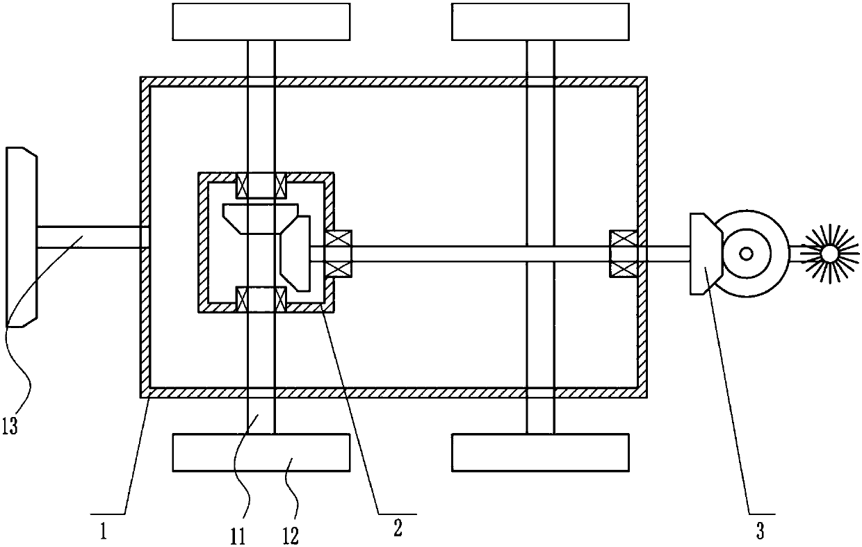
[0026] A leaf cleaning device vehicle, such as Figure 1-4 As shown, it includes a frame 1, an axle 11, wheels 12, a push lever 13, a gear device 2 and a cleaning device 3. The axle 11 of the frame 1 is connected to the wheel 12, and the push lever 13 is at the left end of the frame 1. The device 2 is arranged on the axle 11 and the cleaning device 3 is arranged on the right side of the gear device 2.

Example Embodiment

[0027] Example 2

[0028] A leaf cleaning device vehicle, such as Figure 1-4 As shown, it includes a frame 1, an axle 11, wheels 12, a push lever 13, a gear device 2 and a cleaning device 3. The axle 11 of the frame 1 is connected to the wheel 12, and the push lever 13 is at the left end of the frame 1. The device 2 is arranged on the axle 11 and the cleaning device 3 is arranged on the right side of the gear device 2.

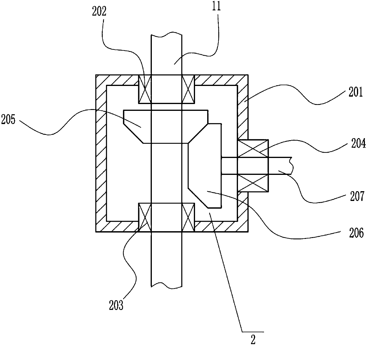
[0029] The gear device 2 includes a first gear box 201, a first bearing 202, a second bearing 203, a third bearing 204, a first bevel gear 205, a second bevel gear 206 and a horizontal shaft 207, a first bearing 202 and a second bearing 203 is symmetrically arranged in the upper and lower positions of the first gear box 201, the axle 11 is arranged on the first bearing 202 and the second bearing 203, the third bearing 204 is arranged on the right side of the first gear box 201, and the first bevel gear 205 is arranged On the axle 11, the second bevel gear 206 me...

Example Embodiment

[0030] Example 3

[0031] A leaf cleaning device vehicle, such as Figure 1-4 As shown, it includes a frame 1, an axle 11, wheels 12, a push lever 13, a gear device 2 and a cleaning device 3. The axle 11 of the frame 1 is connected to the wheel 12, and the push lever 13 is at the left end of the frame 1. The device 2 is arranged on the axle 11 and the cleaning device 3 is arranged on the right side of the gear device 2.

[0032] The gear device 2 includes a first gear box 201, a first bearing 202, a second bearing 203, a third bearing 204, a first bevel gear 205, a second bevel gear 206 and a horizontal shaft 207, a first bearing 202 and a second bearing 203 is symmetrically arranged in the upper and lower positions of the first gear box 201, the axle 11 is arranged on the first bearing 202 and the second bearing 203, the third bearing 204 is arranged on the right side of the first gear box 201, and the first bevel gear 205 is arranged On the axle 11, the second bevel gear 206 me...


PUM


Abstract

The invention relates to a tree leaf sweeping device vehicle and aims at achieving a technical purpose of providing the tree leaf sweeping device vehicle. In order to achieve the technical purpose, the tree leaf sweeping device vehicle includes a vehicle frame and the like; wheels are connected to vehicle shafts of the vehicle frame, a pushing rod is arranged at the left end of the vehicle frame,a gear device is arranged on the vehicle shafts, and a sweeping device is arranged at the right side of the gear device. According to the tree leaf sweeping device vehicle for a garden, by pushing thewheels to rotate, the sweeping device is driven to conduct sweeping and collection treatment on tree leaves on roads and streets in the garden. The sweeping efficiency is greatly improved, the working time is shortened, the manufacturing cost is low, and the operation is easy.

Description

technical field [0001] The invention relates to a cleaning vehicle, in particular to a leaf cleaning device vehicle. Background technique [0002] A garden is a beautiful natural environment and recreational environment created in a certain area by using engineering technology and artistic means to transform the terrain, plant trees and flowers, build buildings, and arrange garden roads. The maintenance and management of gardens and green spaces mainly includes the maintenance and management of plant materials such as trees, flowering shrubs, and lawns in roads, green spaces, and square green spaces, maintenance and management of garden facilities, and special management of commercial and prosperous areas. The maintenance and management work should be carried out in accordance with the growth law and biological characteristics of plant materials and local climatic conditions. [0003] Sweeper is that collection road cleaning, garbage reclamation and transportation are the n...

Claims


Application Information

Patent Timeline
IPC IPC(8): E01H1/04
CPCE01H1/04E01H1/047
Inventor 王静娴丁西飞余津津
Owner 王静娴
Why Eureka
Try Eureka