Wheel flange sealing structure, turbine and gas turbine

A rim and sealing technology, which is applied to gas turbine devices, mechanical equipment, engine components, etc., can solve the problems of unsatisfactory sealing effect and large amount of sealing gas

Active Publication Date: 2018-04-03
AECC COMML AIRCRAFT ENGINE CO LTD
View PDF5 Cites 5 Cited by
  • Summary
  • Abstract
  • Description
  • Claims
  • Application Information

AI Technical Summary

Problems solved by technology

However, although this structure can prevent the backflow of mainstream gas to a certain extent, the sealing effect is not very ideal, and the amount of sealing gas is also relatively large. In order to ensure the sealing effect, the pressure difference of the sealing chamber is required to be high. Therefore, the sealing structure still needs further improvement

Method used


Image

  • Wheel flange sealing structure, turbine and gas turbine
  • Wheel flange sealing structure, turbine and gas turbine
  • Wheel flange sealing structure, turbine and gas turbine

Examples


Embodiment Construction

[0029] The technical solutions in the embodiments of the present invention will be clearly and completely described below in conjunction with the drawings in the embodiments of the present invention. Apparently, the described embodiments are only some of the embodiments of the present invention, not all of them. Based on the embodiments of the present invention, all other embodiments obtained by persons of ordinary skill in the art without making creative efforts fall within the protection scope of the present invention.

[0030] In describing the present invention, it should be understood that the terms "center", "transverse", "longitudinal", "front", "rear", "left", "right", "upper", "lower", " The orientations or positional relationships indicated by "vertical", "horizontal", "top", "bottom", "inner" and "outer" are based on the orientations or positional relationships shown in the drawings, and are only for the convenience of describing the present invention and Simplifie...


PUM


Abstract

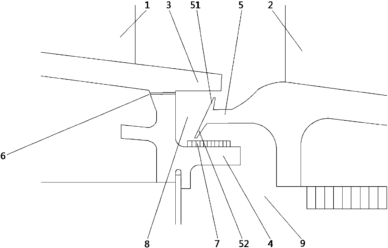
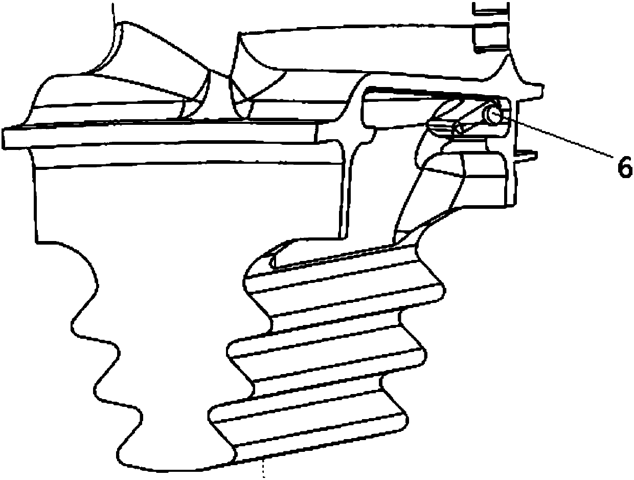
The invention relates to a wheel flange sealing structure, a turbine and a gas turbine. The wheel flange sealing structure comprises a first flange plate (3), a second flange plate (4) and a third flange plate (5), wherein the first flange plate (3) and the second flange plate (4) are arranged at the root part of a movable blade (1), and the third flange plate (5) is arranged at the root part of aguiding blade (2). The first flange plate is closer to the movable blade compared with the second flange plate. The third flange plate extends into an opening formed between the first flange plate and the second flange plate, and the third flange plate forms a first chamber (8) for circulation of sealing gas at least with the first flange plate and the second flange plate. The first chamber (8) is provided with an injector hole (6). The injector hole (6) is used for injecting high-pressure gas into the first chamber (8), wherein the pressure of the high-pressure gas is higher than that of thesealing gas, so that the sealing gas is driven to flow out of the first chamber (8) through jet action of the high-pressure gas. According to the wheel flange sealing structure, the jet action of thehigh-pressure gas is introduced in by forming the injector hole, flowing of the sealing gas is accelerated, the using amount of the sealing gas is decreased, the sealing effect is improved, the requirement for the sealing pressure difference is reduced, and backward flow of main gas is reduced.

Description

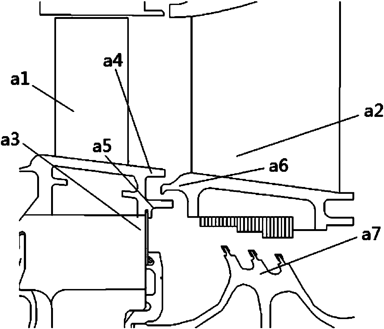
technical field [0001] The invention relates to the technical field of sealing, in particular to a wheel rim sealing structure, a turbine and a gas turbine. Background technique [0002] The sealing of the rim of the gas turbine is a very important structure. The rim seal structure generally entrains air from the compressor to seal the rim of the turbine. The purpose is to prevent the high-temperature gas flowing through the main flow of the turbine from pouring back into the disk cavity and causing ablation of the turbine disk. The amount of bleed air from the compressor also needs to be strictly controlled. If the amount of bleed air is too small, it may lead to the backflow of mainstream gas; if the amount of bleed air is too large, it will affect the overall performance of the gas turbine. Strict effect is an important part of engine design. [0003] At present, the rim sealing basically adopts the fish mouth type sealing structure, such as figure 1 As shown, the movi...

Claims


Application Information

Patent Timeline
Patent Type & Authority Applications(China)
IPC IPC(8): F01D11/06F02C7/28
Inventor 吴丽军
Owner AECC COMML AIRCRAFT ENGINE CO LTD
Why Eureka
Try Eureka