Multistage multimode mechanical and hydraulic continuously variable transmission

A continuously variable transmission, mechanical transmission technology, applied in mechanical equipment, fluid transmission, belt/chain/gear, etc., to achieve the effect of flexible switching control, maintaining stability, and improving power performance

Inactive Publication Date: 2018-04-03
HENAN UNIV OF SCI & TECH
View PDF5 Cites 12 Cited by
  • Summary
  • Abstract
  • Description
  • Claims
  • Application Information

AI Technical Summary

Problems solved by technology

Single use of mechanical transmission or hydraulic transmission is difficult to perfectl...

Method used


Image

  • Multistage multimode mechanical and hydraulic continuously variable transmission
  • Multistage multimode mechanical and hydraulic continuously variable transmission
  • Multistage multimode mechanical and hydraulic continuously variable transmission

Examples


Embodiment 1

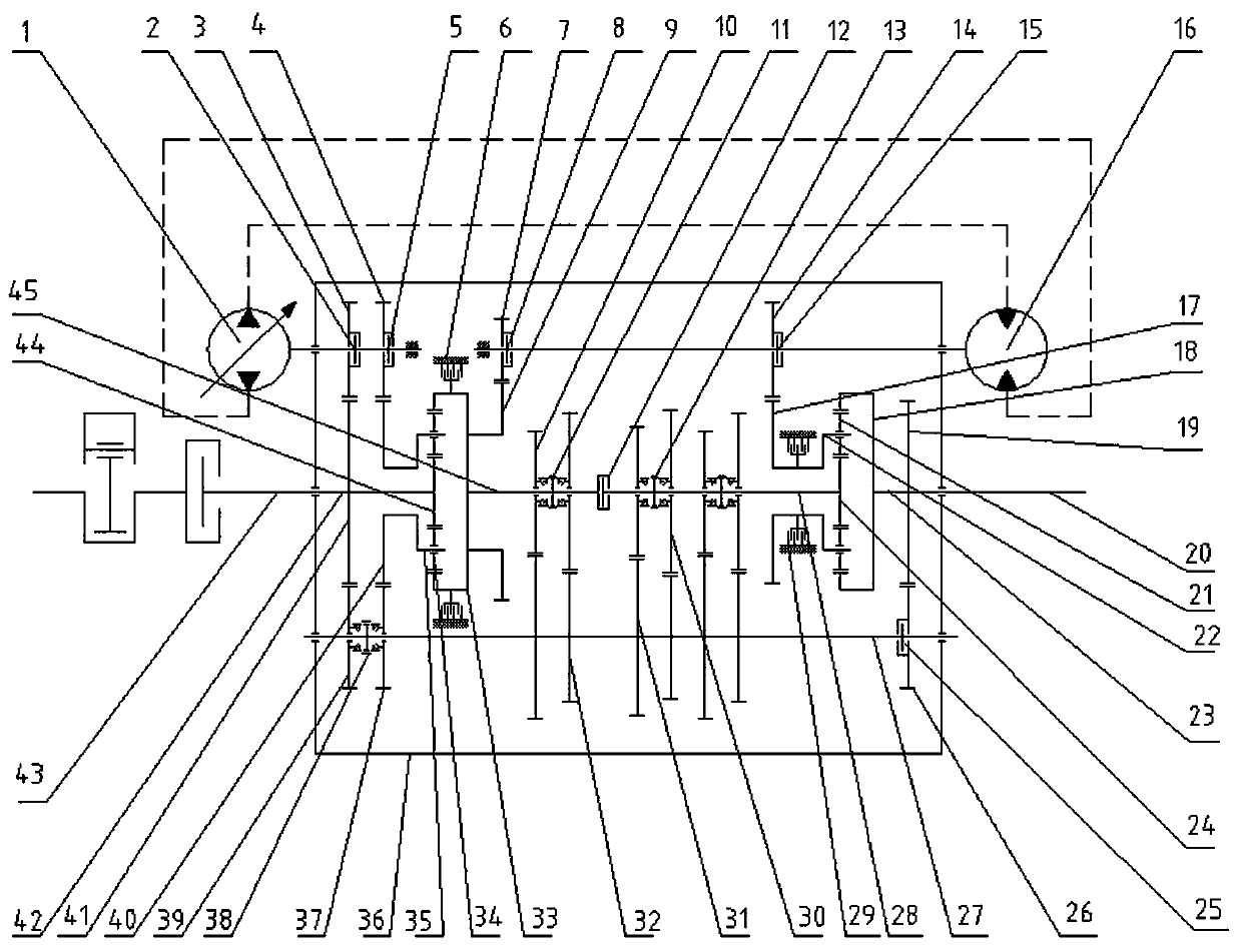
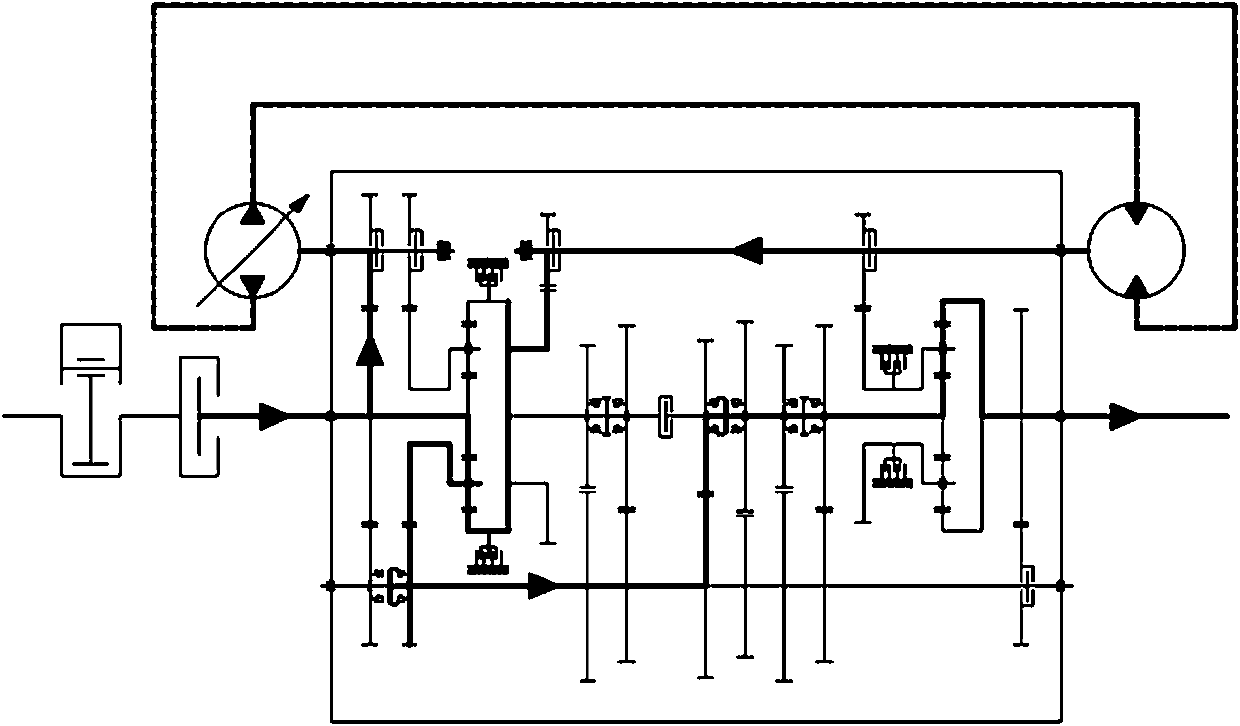
[0034] Embodiment 1. The first hydromechanical diversion and confluence form of a multi-stage multi-mode mechanical and hydraulic continuously variable transmission: the power is diverted at the thirteenth gear 3 and the first gear 41, and the confluence is realized at the front planetary row. The final power passes through the rear planetary row to output power. Specifically, such as figure 2 As shown, the power transmitted from the engine realizes torque splitting at the first gear 41, all the way through the thirteenth gear 3 and the engaged first clutch 2 to the variable displacement hydraulic pump 1, and then through the hydraulic pipeline, quantitative The hydraulic motor 16, the third clutch 8, the fifteenth gear 7 and the third gear 9 transmit power to the front ring gear 33 of the front planetary row; one way transmits power to the front sun gear 44; The speed confluence is realized by the row, and the power after confluence passes through the third gear 9, the firs...

Embodiment 2

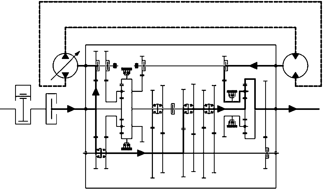
[0038] Embodiment 2. A second type of hydromechanical branching and converging form of a multi-stage multi-mode mechanical and hydraulic continuously variable transmission: the power realizes torque splitting at the thirteenth gear 3, the first gear 41 and the eighth gear 39, and passes through the hydraulic circuit 1. The speed confluence is realized at the rear planetary row, and the power is output through the main output shaft 20 after the confluence. Specifically, such as image 3 As shown, the power transmitted from the engine realizes torque splitting at the first gear 41, all the way through the thirteenth gear 3 and the closed first clutch 2 to the variable displacement hydraulic pump 1, and then through the hydraulic pipeline, quantitative The hydraulic motor 16, the fourth clutch 15, the sixteenth gear 14 and the sixth gear 17 transmit power to the rear planetary carrier 22 of the rear planetary row; all the way through the eighth gear 39 and the first synchronizer ...

Embodiment 3

[0042] Embodiment 3. The third hydromechanical diversion and confluence form of a multi-stage multi-mode mechanical and hydraulic continuously variable transmission: the power is diverted at the front planetary row, and the confluence is realized at the rear planetary row through the hydraulic circuit. After converging, it passes through the main output Shaft 20 outputs power. Specifically, such as Figure 4 As shown, the power transmitted from the engine realizes torque splitting at the front planetary row, all the way through the fourteenth gear 4 and the closed second clutch 5 to the variable displacement hydraulic pump 1, and then through the hydraulic pipeline, quantitative hydraulic pressure The motor 16, the fourth clutch 15, and the sixteenth gear 14 transmit power to the rear planetary carrier 22 of the rear planetary row; all the way through the ninth gear 37 and the first synchronizer 38 to the transmission gear shaft 27, and then through one of them in turn The el...


PUM


Abstract

The invention relates to the field of vehicle engineering variable transmission equipment, in particular to a multistage multimode mechanical and hydraulic continuously variable transmission comprising a shell, a double planetary row mechanical transmission and a hydraulic transmission, and the double planetary row mechanical transmission and the hydraulic transmission are arranged in the shell ina parallel connection mode. A mode gear switching execution system is further arranged in the shell and is used for controlling independent variable output of the double planetary row mechanical transmission or for controlling independent variable output of the hydraulic transmission or for controlling mixed variable output of the double planetary row mechanical transmission and the hydraulic transmission. The multistage multimode mechanical and hydraulic continuously variable transmission aims at overcoming the defects existing in the prior art, can achieve multistage large-range continuously variable performance, and also can meet the multimode requirements for a vehicle driven under different operation conditions.

Description

technical field [0001] The invention relates to the field of variable speed transmission equipment for vehicle engineering, in particular to a multi-stage multi-mode mechanical and hydraulic continuously variable transmission. Background technique [0002] Hydraulic transmission has the advantages of convenient layout, high power density, output torque and speed are not affected by input speed, easy to realize stepless speed regulation and automatic control, etc., but at the same time, it has the disadvantages of low transmission efficiency, especially in high speed and low speed. In the transmission working condition, the deficiency of low transmission efficiency is more prominent. Gear mechanical transmission has the advantages of accurate and reliable transmission motion, constant instantaneous transmission ratio, compact structure, large transmission ratio, large transmission power and high transmission efficiency, but it is not easy to realize automatic transmission, le...

Claims


Application Information

Patent Timeline
IPC IPC(8): F16H47/04
CPCF16H47/04
Inventor 曹付义李豪迪张风丽王浩然马可崔梦凯李金龙
Owner HENAN UNIV OF SCI & TECH
Why Eureka
Try Eureka