
Air purifier and achieving method thereof

An air purifier and air technology, applied in the field of indoor air purification, can solve problems such as excessive size, damaged temperature sensor, and high temperature

Inactive Publication Date: 2018-04-03
JIANGSU UNIV OF SCI & TECH
View PDF8 Cites 6 Cited by
  • Summary
  • Abstract
  • Description
  • Claims
  • Application Information

AI Technical Summary

Problems solved by technology

[0007] As we all know: adopting heating desorption to adsorbent material is the method generally adopted by those skilled in the art, in order to overcome the defect that the adsorption type purifier needs to frequently replace the adsorbent material, and according to the method of adsorbent material heating desorption, currently there are public literature records to collect heat A new type of adsorption purifier with desorption function integrated, such as the patent application number: 201510898501.0, a wall-mounted air purifier based on thermal regeneration and its purification method. Users can choose indoor purification or mechanical ventilation according to their needs. When choosing When the indoor purification function is used, the sewage will be discharged after thermal desorption during the working process. When the mechanical ventilation function is selected, the outdoor fresh air will be introduced into the room. However, the wall-mounted air purifier and its purification method have the following defects: When it is attached (heat regeneration mode period), the pressure in the closed airtight cabin may be too high, and because the pressure relief valve for preventing device damage is installed on the wall of the air purification room of the airtight cabin of the purifier to the room, once the pressure is released When the valve is opened to release the pressure, the air with high concentration of pollutants in the cabin will be released to the room, causing secondary pollution in the room, and when the air valve between the air purification room and the heating regeneration room is closed and the heating regeneration room leads The outdoor air valve is closed, that is, when the purifier is in the purification mode, the heating control circuit of the electric heating wire in the heating and regeneration chamber loses control and generates high temperature, and the temperature sensor in the heating and regeneration chamber is damaged. At this time, the closed heating and regeneration chamber generates The pressure may be too high and damage the device, because the pressure relief valve installed on the wall of the air purification room facing the room cannot work at this moment; The temperature is the indoor air temperature, so when the outdoor temperature is higher than the indoor temperature, the outdoor air temperature cannot be used as the initial temperature of the air in the cabin when the thermal desorption starts, that is, the outdoor high-temperature air cannot be introduced into the cabin when the thermal desorption starts , so that the initial temperature of the air in the cabin is consistent with the temperature of the high-temperature outdoor air, so when the outdoor temperature is higher than the indoor temperature, the method that the initial temperature of the air in the cabin is the indoor air temperature when the thermal desorption is started is now adopted, so that when desorption No energy saving; (3) Since the air valve at the top of the air purification chamber is opened in the blowdown mode, and the air valve at the bottom of the air purification chamber is closed, the desorbed pollutant-containing air in the air purification chamber cannot be completely discharged. It may also be exhausted indoors, causing secondary pollution; (4) Since the air valve at the bottom of the air purification room is opened in the fresh air mode, and the air valve at the top of the air purification room is closed, the outdoor fresh air cannot pass through the air. The filter module in the main body of the channel is purified and then introduced into the room, but directly into the room without being purified by the filter module; (5) Due to the use of pure timing sewage discharge, the timing time may be too long or too short, such as the timing time may be too long in winter, and the timing time may be too short in summer. There may be a timed time that the heat in the nacelle cannot be dissipated; ⑹ there is no dust removal function for the dust adsorbed on the coarse filter

Method used


Image

  • Air purifier and achieving method thereof
  • Air purifier and achieving method thereof

Examples


Embodiment Construction

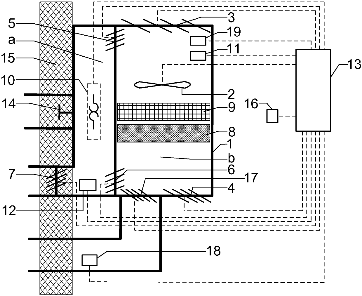
[0055] Such as figure 1 As shown, an air purifier includes: an airtight cabin 1, a fan 2, a first electrically controlled air valve 3, a second electrically controlled air valve 4, a third electrically controlled air valve 5, a fourth electrically controlled air valve 6, The fifth electronically controlled air valve 7, the sixth electronically controlled air valve 17, the coarse filter 8, the high-efficiency renewable VOCs and formaldehyde adsorption material 9, the heating element 10, the VOCs sensor 11, the flow sensor 19, the first temperature sensor 12, The second temperature sensor 16, the third temperature sensor 18, the control processor unit 13, the pressure relief valve 14; the first temperature sensor 12, the second temperature sensor 16, the third temperature sensor 18, the VOCs sensor 11 and the flow sensor 19 They are respectively connected to the input ends of the control processor unit 13; the first electrically controlled air valve 3, the second electrically co...


PUM


Abstract

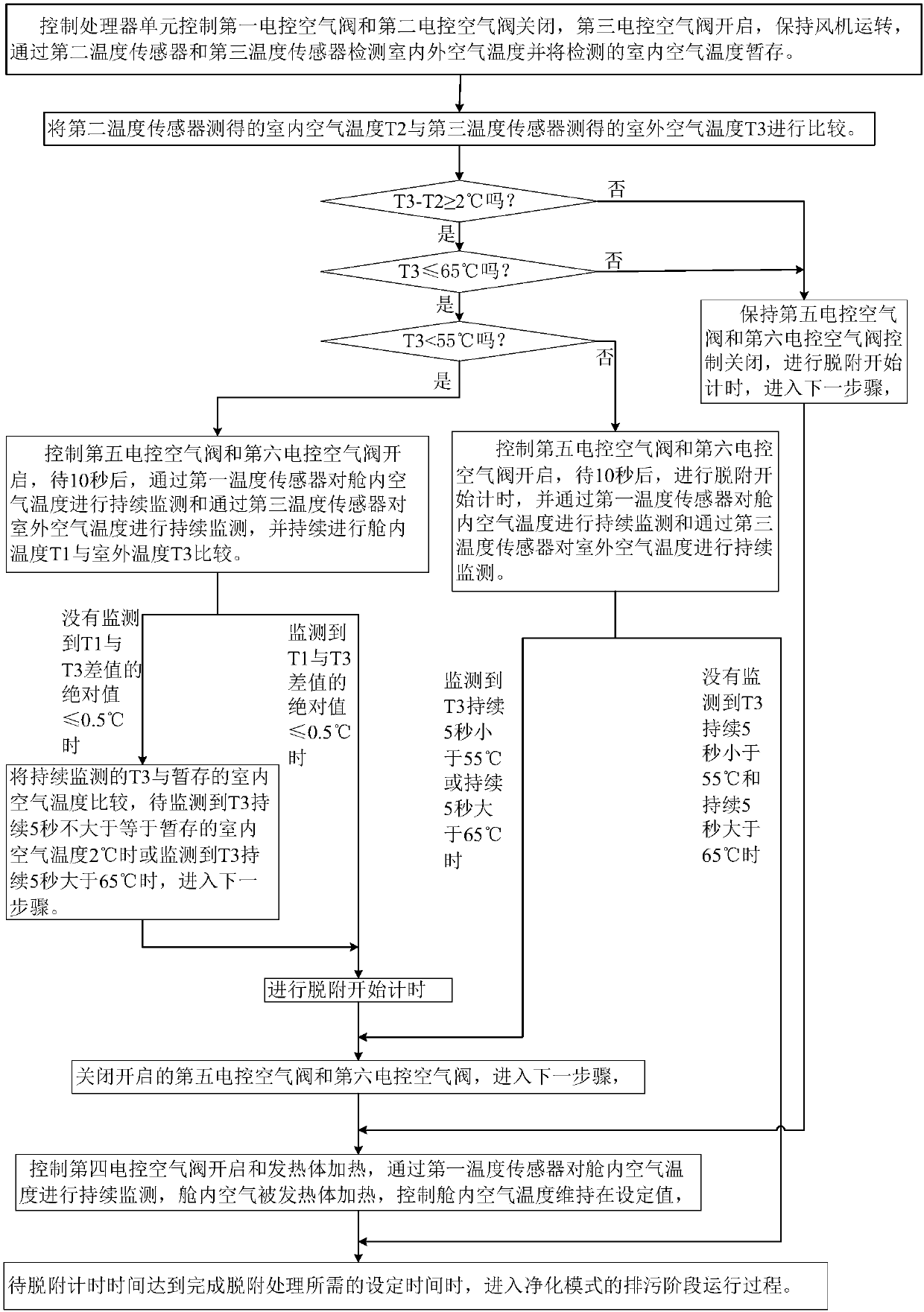
The invention discloses an air purifier and an achieving method thereof. The air purifier comprises a sealed cabin divided into a left heating regeneration chamber and a right air purification chamber, and a pressure release valve, air channels and sensors are arranged on the cabin wall of the sealed cabin, wherein the pressure release valve is mounted on the cabin wall of the heating regenerationchamber and communicates with the outdoor space in a through-wall mode, the air channels controlled by electric-control air valves to be opened / closed to communicate with the outdoor space in a through-wall mode are formed in the lower wall of the air purification chamber, and the sensors for measuring the air temperature are arranged in indoor and outdoor spaces correspondingly. According to theachieving method, during pressure releasing of the pressure release valve, secondary pollution cannot occur to the indoor space; when desorption is conducted, if the outdoor air temperature is largerthan the indoor air temperature but smaller than or equal to 65 DEG C, outdoor air enters the cabin, so that the outdoor temperature serves as the initial temperature during desorption or directly serves as the desorption temperature; the pollution discharge duration is controlled through a timing temperature increasing and measuring method, and it is ensured that after pollution discharge is finished, the cabin interior temperature adapts to the indoor temperature; in the pollution discharge process, dust removal is achieved through control over positive and negative rotation of a draught fan; and whether blocking occurs or not is distinguished according to the flow rate, and real-time dust removal is achieved.

Description

technical field [0001] The invention belongs to the technical field of indoor air purification, and in particular relates to the structural design and realization method of a heat-regenerating wall-mounted air cleaner. Background technique [0002] With the rapid development of urbanization in our country, the number of new buildings is huge every year, and more and more new decoration materials and chemical products are used in interior decoration. These new interior decoration materials often release a large amount of pollutants such as volatile organic compounds (VOCs) and formaldehyde, causing serious indoor pollution. According to statistics, after decoration, most of the formaldehyde and VOCs content in newly built houses exceeds the standard. [0003] Volatile organic compounds (VOCs) and formaldehyde significantly affect people's comfort, health and work efficiency. Volatile organic compounds cause sensory stimulation to the human body, make the human body feel dry...

Claims


Application Information

Patent Timeline
IPC IPC(8): F24F1/02F24F13/20F24F13/00F24F11/89F24F13/28B01D53/04B01D46/10
CPCF24F1/02B01D46/10B01D53/02B01D2257/708B01D2258/06B01D2259/40088B01D2259/4508F24F13/00F24F13/20F24F13/28
Inventor 张笑非王长宝罗浩张静胡广朋
Owner JIANGSU UNIV OF SCI & TECH
Learn More