
Shell-and-tube heat exchanger with condensable vapor phase and provided with multi-tube flow-stabilizing device

A shell-and-tube heat exchanger and flow stabilization device technology, applied in indirect heat exchangers, heat exchanger types, fixed tubular conduit components, etc., can solve strong vibration, impact equipment and pipes, low heat exchange efficiency, etc. problems, to achieve the effect of reducing noise and vibration, improving heat exchange effect, and stabilizing flow

Inactive Publication Date: 2018-04-03
SHANDONG UNIV
View PDF4 Cites 23 Cited by
  • Summary
  • Abstract
  • Description
  • Claims
  • Application Information

AI Technical Summary

Benefits of technology

This patented technology helps reduce vibrations and noises during high temperature refrigerant systems used for air conditioners or similar applications that use multiple tubes filled with different fluids like water/refrigerants. It also includes an improved design that separates both phases without any separation walls inside them while still allowing some liquids from one stream to pass through but prevented others from doing this effectively. Additionally, there may be variations in these designs based upon factors such as pressure drop across each component's membrane, size of bubble formation points within the system, etc., resulting in better performance at reduced temperatures compared to previous methods. Overall, this innovation makes efficient operation more reliable over time due to its ability to improve energy efficiency and minimize vibrating sound levels.

Problems solved by technology

The technical problem addressed by this patented design for improving the stability or smoothness of fluids during evaporation/condenser systems has been solved through an improved heat transfer system that uses a special type of tube called a stable flow straightener (SL) instead of traditional methods like mixing them together before they enter into contact between different parts inside the machine's chamber. This results in more efficient coolant circulation without compromising its effectiveness due to turbulence caused by unevenly distributed phases within it.

Method used


Image

  • Shell-and-tube heat exchanger with condensable vapor phase and provided with multi-tube flow-stabilizing device
  • Shell-and-tube heat exchanger with condensable vapor phase and provided with multi-tube flow-stabilizing device
  • Shell-and-tube heat exchanger with condensable vapor phase and provided with multi-tube flow-stabilizing device

Examples


Embodiment Construction

[0038] The specific embodiments of the present invention will be described in detail below in conjunction with the accompanying drawings.

[0039] In this article, if there is no special explanation, when it comes to formulas, " / " means division, and "×" and "*" mean multiplication.

[0040] It should be noted that, unless otherwise specified, the two-phase flow mentioned in the present invention is a vapor-liquid two-phase flow, where the vapor phase can be condensed into a liquid phase during the heat exchange process.

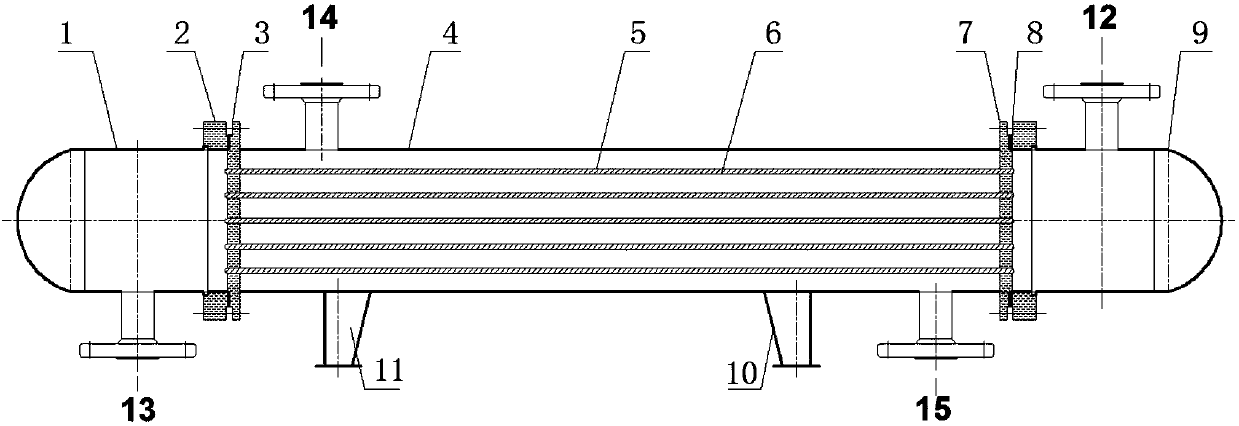
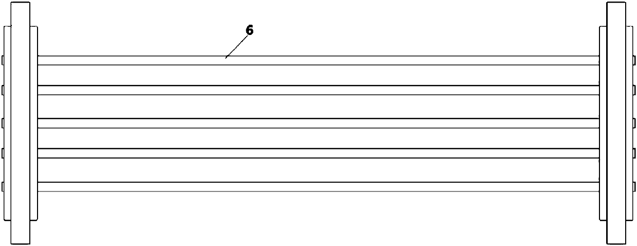
[0041] Such as figure 1 A shell-and-tube heat exchanger is shown, and the shell-and-tube heat exchanger includes a shell 4, a heat exchange tube 6, a tube-side inlet pipe 12, a tube-side outlet pipe 13, a shell-side inlet connecting pipe 14 and a shell The outlet connecting pipe 15; the heat exchange tube bundle composed of a plurality of parallel heat exchange tubes 6 is connected to the front tube sheet 3 and the rear tube sheet 7; the front end of the fr...


PUM


Abstract

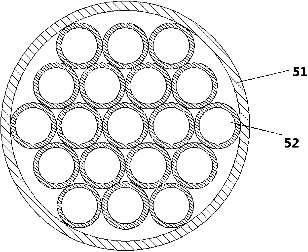
The invention provides a multi-tube shell-and-tube heat exchanger with vapor-liquid two-phase flow. The multi-tube shell-and-tube heat exchanger comprises a shell body, wherein sealing heads are arranged at the two ends of the shell body separately; a tube plate is arranged at the connection position of each sealing head and the shell body; a heat exchange tube is connected with the tube plates atthe two ends; and a vapor phase in the vapor-liquid two-phase flow can be condensed into a liquid phase in a heat exchange process. The multi-tube shell-and-tube heat exchanger is characterized in that a flow-stabilizing device is arranged in the heat exchange tube; the flow-stabilizing device comprises a core body and a housing; the core body is arranged in the housing; the housing is connectedand fixed to the inner wall of the heat exchange pipe; and the core body is combined through adjacently connecting a plurality of tubes. The invention provides a heat exchanger with a novel structureand provided with a flow-stabilizing device. In the case of vapor-liquid two-phase flowing in a pipeline, heat transfer is enhanced, and meanwhile, the vibration of the pipeline is weakened, and the noise level is lowered.

Description


Claims


Application Information

Patent Timeline
Owner SHANDONG UNIV
Learn More