Optical axis alignment device and method based on camera imaging

A camera imaging and alignment device technology, which is applied in the field of optical engineering, can solve problems such as the inability to balance easy operation and alignment accuracy, and achieve the effect of easy operation and high precision

Active Publication Date: 2018-04-03
XI'AN INST OF OPTICS & FINE MECHANICS - CHINESE ACAD OF SCI
View PDF7 Cites 7 Cited by
  • Summary
  • Abstract
  • Description
  • Claims
  • Application Information

AI Technical Summary

Problems solved by technology

[0003] The purpose of the present invention is to provide an optical axis alignment device and optical axis alignment method based on camera imaging, w

Method used


Image

  • Optical axis alignment device and method based on camera imaging
  • Optical axis alignment device and method based on camera imaging
  • Optical axis alignment device and method based on camera imaging

Examples


Embodiment Construction

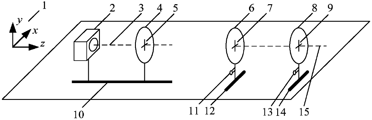
[0030] see figure 1 , the present invention provides an optical axis alignment device based on camera imaging and an optical axis alignment method. The structure of the preferred embodiment of the optical axis alignment device includes No. 1 guide rail 10, No. Guide rail 12 and No. 3 guide rail 14, No. 2 guide rail 12 is parallel to No. 3 guide rail 14 and perpendicular to No. 1 guide rail 10;

[0031] Camera 2 and No. 1 reticle 4 are installed on the No. 1 guide rail 10, No. 2 reticle 6 is installed on No. 2 guide rail 12, and No. 3 reticle 8 is installed on No. 3 guide rail 14; Camera 2 can select SLR camera for use, one No. reticle 4, No. 2 reticle 6 and No. 3 reticle 8 are cross reticles.

[0032] The camera 2 can slide freely along the No. 1 guide rail 10, the No. 1 reticle 4 is fixedly installed on the No. 1 guide rail 10, and the optical axis where the cross center 5 of the No. 1 reticle and the camera lens center is located is the fixed optical axis 3;

[0033] No. 2...


PUM


Abstract

The invention belongs to the technical field of optical engineering and particularly relates to an optical axis alignment device and method based on camera imaging. The optical axis alignment device comprises a first guide rail, a second guide rail, a third guide rail and a computer, wherein the first, second and third guide rails are arranged sequentially in a same horizontal plane and the computer is used for analyzing camera image coordinates; the second guide rail is parallel to the third guide rail and perpendicular to the first guide rail; a camera and a first division plate are mountedon the first guide rail, a second division plate is mounted on the second guide rail, and a third division plate is mounted on the third guide rail; an optical axis where the center of the first division plate and the center of a lens of the camera locate is a fixed optical axis; an optical axis where the center of the second division plate and the center of the third division plate locate is an adjustable optical axis. An imaging method is used in alignment and is as precise as alignment by direct observation via a theodolite and is universal in engineering applications.

Description

technical field [0001] The invention belongs to the technical field of optical engineering, and in particular relates to an optical axis alignment device and an optical axis alignment method based on camera imaging. Background technique [0002] In the field of optical engineering technology, it is often necessary to calibrate and calibrate the optical axis. Traditional optical axis alignment methods use the linear propagation characteristics of light and require the help of various calibration instruments. For example, when laser is used for optical axis alignment, it can be considered that the positions passed by the laser are all on the same optical axis. The laser has the advantages of simple structure, small size, and convenient operation. However, since the laser spot diameter has a certain size, and the farther the propagation distance is, the larger the spot diameter is, it is difficult to accurately align the optical axis, so the laser alignment method is only appli...

Claims


Application Information

Patent Timeline
IPC IPC(8): G02B27/36
CPCG02B27/36
Inventor 吴国俊刘博吴亚风吕沛刘巍王皓郝歌扬
Owner XI'AN INST OF OPTICS & FINE MECHANICS - CHINESE ACAD OF SCI
Why Eureka
Try Eureka