Photoelectric composite cable and manufacture method and application thereof

A technology for optoelectronic composite cables and cable cores, which is applied in the manufacture of cables/conductors, power cables including optical transmission elements, power cables, etc.

Pending Publication Date: 2018-04-03
SHANGHAI FEIHANG ELECTRIC WIRE & CABLE
View PDF0 Cites 1 Cited by
  • Summary
  • Abstract
  • Description
  • Claims
  • Application Information

AI Technical Summary

Problems solved by technology

[0003] The existing electric vehicle conductive charging system cables mainly use copper conductors as signal and control cores. There are two ways to shield: bare copper wire or tinned copper wire braide

Method used


Image

  • Photoelectric composite cable and manufacture method and application thereof
  • Photoelectric composite cable and manufacture method and application thereof
  • Photoelectric composite cable and manufacture method and application thereof

Examples


Embodiment 1

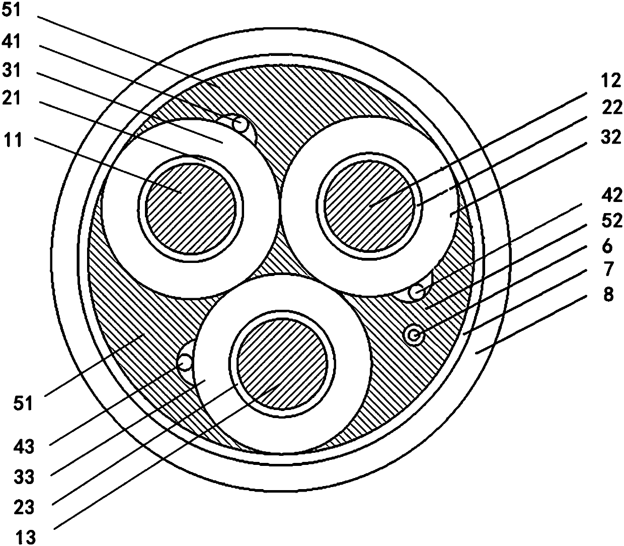
[0055] A kind of photoelectric composite cable, the structural diagram is shown in the attached figure 1 , which includes a cable core and a polyester tape 7 and an outer sheath 8 that are sequentially coated on the outside of the cable core; wherein the cable core includes a first insulated core with a first metal central tube type temperature measuring optical unit 41 attached to the outside , the second insulated wire core of the second metal central tube type temperature measuring optical unit 42 is attached on the outside, the third insulated core of the third metal central tube type temperature measuring optical unit 43 and the non-metallic central tube type The communication optical unit 6; the first insulated wire core, the second insulated wire core and the third insulated wire core are in contact with each other;

[0056] Wherein, the first insulated wire core is composed of a conductor 11 and an isolation layer coated on the outside of the conductor 11, and the isol...

Embodiment 2

[0075] A kind of photoelectric composite cable, the structural diagram is shown in the attached Figure 4 , which includes a cable core and a polyester tape 7 and an outer sheath 8 that are sequentially coated on the outside of the cable core; wherein the cable core includes a first insulated core with a first metal central tube type temperature measuring optical unit 41 attached to the outside , the second insulated wire core of a second metal central tube type temperature measurement optical unit 42 is attached to the outside, and the third insulated core of the third metal central tube type temperature measurement optical unit 43 and the non-metallic central tube type are attached to the outside. The communication optical unit 6; the first insulated wire core, the second insulated wire core and the third insulated wire core are in contact with each other;

[0076] Wherein, the first insulated wire core is composed of a conductor 11 and an isolation layer coated on the outsi...

Embodiment 3

[0095] A kind of photoelectric composite cable, the structural diagram is shown in the attached figure 1 , which includes a cable core and a polyester tape 7 and an outer sheath 8 that are sequentially coated on the outside of the cable core; wherein the cable core includes a first insulated core with a first metal central tube type temperature measuring optical unit 41 attached to the outside , the second insulated wire core of the second metal central tube type temperature measuring optical unit 42 is attached on the outside, the third insulated core of the third metal central tube type temperature measuring optical unit 43 and the non-metallic central tube type The communication optical unit 6; the first insulated wire core, the second insulated wire core and the third insulated wire core are in contact with each other;

[0096]Wherein, the first insulated wire core is composed of a conductor 11 and an isolation layer coated on the outside of the conductor 11, and the isola...


PUM

PropertyMeasurementUnit
Areaaaaaaaaaaa
Outer diameteraaaaaaaaaa
Areaaaaaaaaaaa

Abstract

The invention discloses a photoelectric composite cable and its manufacturing method and application. The photoelectric composite cable includes a cable core and a polyester tape and an outer sheath that are sequentially coated on the outside of the cable core; Metal center tube type communication optical unit; three insulated wire cores are in contact with each other; the gap formed by the cable core and polyester tape is filled with filler; there is also an opening in the filler, and the metal center tube type temperature measurement optical unit is set in the opening. The manufacturing method is to combine three insulated wire cores, three metal central tube-type temperature measuring optical units and non-metallic central tube-type communication optical units into a cable core, fill the gap of the cable core with filler, then wrap polyester tape, and extrude The outer sheath is sufficient. The photoelectric composite cable of the present invention integrates temperature measurement, early warning and communication, can realize the monitoring of each insulated wire core and the monitoring is more accurate, and the cable structure is more compact.

Description

technical field [0001] The invention relates to a photoelectric composite cable and its manufacturing method and application. Background technique [0002] China's new energy vehicles started late. Although the country has been vigorously promoting them, the development of new energy vehicles was still relatively slow from 2008 to 2014 due to restrictions on battery and other technologies. After entering 2014, it is defined as the first year of commercialization of charging piles. After the development in 2015, new energy vehicles and charging stations, especially charging piles, are expected to experience explosive growth in 2016, three times the production volume in 2015. As a supporting product for new energy electric vehicles and charging pile power transmission, the charging pile cable will also usher in new markets and opportunities for its development. [0003] The existing electric vehicle conductive charging system cables mainly use copper conductors as signal and...

Claims


Application Information

Patent Timeline
IPC IPC(8): H01B9/00H01B7/32H01B13/00
CPCH01B9/003H01B7/32H01B7/324H01B9/005H01B13/00
Inventor 胡少中石磊
Owner SHANGHAI FEIHANG ELECTRIC WIRE & CABLE
Why Eureka
Try Eureka