Surgical lithotomy position leg support

A technology of lithotomy position and leg support, which is applied in the field of medical equipment, can solve the problems affecting the operation process, complex operation, and easily damaged locking structure, etc., and achieve the effect of simple overall structure, large clamping area, and elimination of tangential force

Pending Publication Date: 2018-04-06
河南正源医疗装备有限公司
View PDF0 Cites 2 Cited by
  • Summary
  • Abstract
  • Description
  • Claims
  • Application Information

AI Technical Summary

Problems solved by technology

[0003] Operating bed accessories such as leg frames are used by being fixed on the side rails on both sides of the operating bed. For ease of use, the size of the operating bed side rails is generally set in the following specifications: section 30*10mm, 30*8mm, 25* 10mm, 25*8mm, there are two fixing methods of the existing leg frame fixing device: one is the up and down adjustable screw fixing, this fixing method can only fasten the vertical direction, and cannot fasten the horizontal direction, so the fixation is not firm , once it falls off during the operation, it will cause great harm to the patient; the second is the two-way adjustable screw fixation, although this method can fasten the horizontal and vertical directions at the same time, but the operation is complicated, and the two directions need to be adjusted in coordination, and the pressure area fixed by the screw Small, unstable, and prone to irreversible damage to side rails
[0004] The movement and locking method of the existing lithotomy position leg frame is the cooperation of the eccentric shaft and the eccentric mandrel. Through the working stroke of the eccentric wheel rotation, the hemispherical bearing is moved or locked by the pressure through the eccentric mandrel. However, the existing eccentric shaft The ejector rod in the structure is a simple one-piece column. There are two problems in this des

Method used


Image

  • Surgical lithotomy position leg support
  • Surgical lithotomy position leg support
  • Surgical lithotomy position leg support

Examples


Embodiment Construction

[0040] In order to understand the above-mentioned purpose, features and advantages of the present invention more clearly, the present invention will be further described in detail below in conjunction with the accompanying drawings and specific embodiments. It should be noted that, in the case of no conflict, the embodiments of the present application and the features in the embodiments can be combined with each other.

[0041] In the following description, many specific details are set forth in order to fully understand the present invention. However, the present invention can also be implemented in other ways different from those described here. Therefore, the protection scope of the present invention is not limited by the specific details disclosed below. EXAMPLE LIMITATIONS.

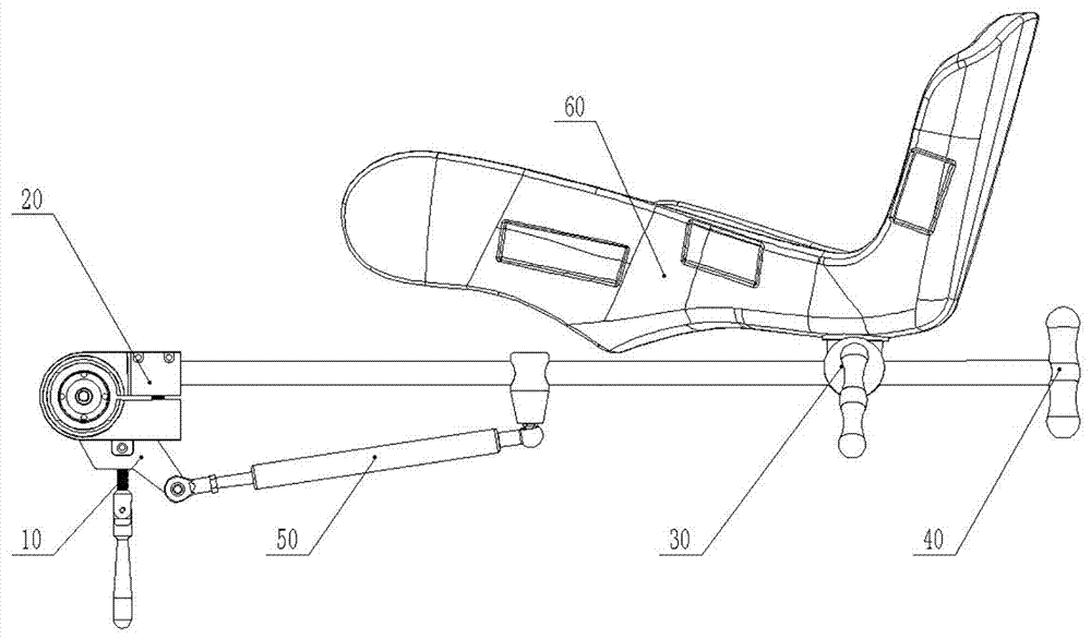
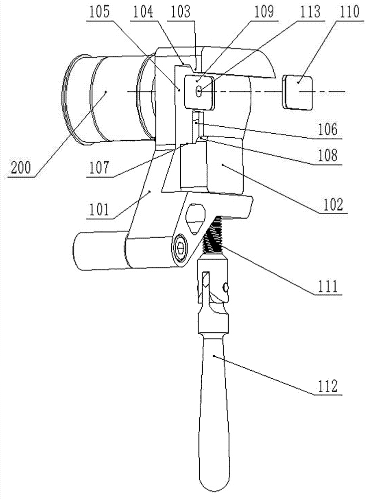
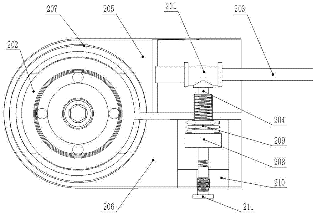
[0042] Such as Figure 1~Figure 8 As shown, the surgical lithotomy position leg frame of the present invention includes a side rail clip 10, an eccentric locking structure 20, and a leg support lockin...


PUM


Abstract

The invention provides a leg frame for lithotomy position, which includes a side rail clamp, an eccentric locking structure, and a leg support locking structure. The side rail clamp includes a side rail clamp main body, an adjustable clamping block, and a handle assembly. The rail clip is provided with backing plate grooves, which are used to place the backing plate; the eccentric locking structure includes locking devices, hemispherical bearings, eccentric shafts, and eccentric ejector rods, and the eccentric ejector rods include top sheet, connecting rod, stage clip, and tail jack post, and the top sheet is hinged with the connecting rod. The leg frame of the present invention is more stable in clamping, adapts to different operating bedside rails, eliminates the tangential force of the eccentric wheel on the ejector rod, and prolongs the service life of the leg frame. If the tightening device is damaged, the leg rest can be adjusted with multiple degrees of freedom, and the locking method is easy to operate; the structure is beautiful and simple, the operation is simple, and the structure is simple, so as to avoid affecting the operation process.

Description

technical field [0001] The invention relates to the technical field of medical instruments, in particular to a leg support for lithotomy position. Background technique [0002] The leg support is an important medical device in lithotomy position surgery. The traditional leg support supports the popliteal part of the patient's leg. Due to the small support area of ​​this kind of leg support, it is easy to cause blood circulation disturbance in the patient's leg. The leg support for the calf support This secondary injury can be avoided, hence the increasing popularity of calf support leg braces. [0003] Operating bed accessories such as leg frames are used by being fixed on the side rails on both sides of the operating bed. For ease of use, the size of the operating bed side rails is generally set in the following specifications: section 30*10mm, 30*8mm, 25* 10mm, 25*8mm, there are two fixing methods of the existing leg frame fixing device: one is the up and down adjustable ...

Claims


Application Information

Patent Timeline
IPC IPC(8): A61G13/12
CPCA61G13/1245A61G13/126
Inventor 朱东海王仲景牛金岭李强贾天天
Owner 河南正源医疗装备有限公司
Why Eureka
Try Eureka