Internal cooling fiber vibrating wire grid type centrifugal demister

A kind of technology of fiber grid and mist eliminator

Active Publication Date: 2018-04-06
QINGDAO UNIV +1
View PDF15 Cites 8 Cited by
  • Summary
  • Abstract
  • Description
  • Claims
  • Application Information

AI Technical Summary

Problems solved by technology

[0003] The purpose of the present invention is to overcome the deficiencies of the prior art, seek to provide an internal cooling fiber vibrating wire grid type centrifugal demister, solve the problem of low efficiency and high investment cost of the demister, and learn from the vibrating wire type to capture fine mist The theor

Method used


Image

  • Internal cooling fiber vibrating wire grid type centrifugal demister
  • Internal cooling fiber vibrating wire grid type centrifugal demister
  • Internal cooling fiber vibrating wire grid type centrifugal demister

Examples


Embodiment 1

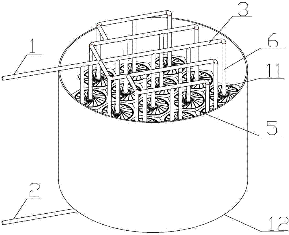
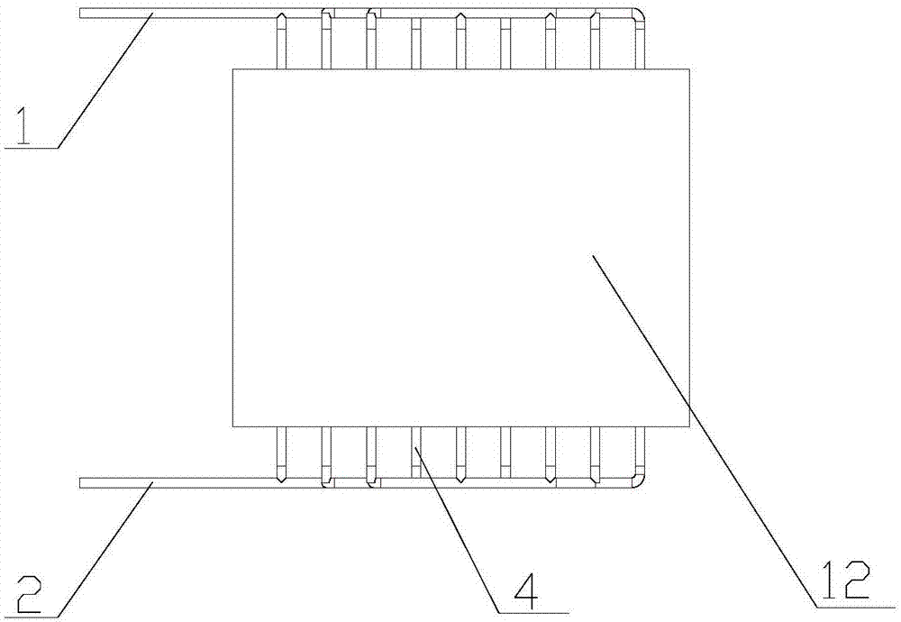
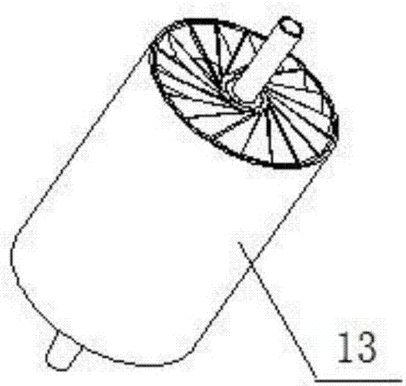
[0024] The main structure of the internal cooling fiber vibrating wire grid type centrifugal demister involved in this embodiment includes an air inlet pipe 1, an air outlet pipe 2, an air distribution pipe 3, an air collection pipe 4, a support plate 5, a cooling water pipe 6, and a demister unit 13 And the first cylinder 12, the first cylinder 12 is vertically provided with a plate-shaped support plate 5, the size and structure are the same and adjacent support plates 5 are connected end to end to form a hollow prism structure, and more than one size structure is the same The hollow prisms form a honeycomb structure, and each hollow prism is equipped with a defogging unit 13. The defogging unit 13 includes a first bearing 7, a second bearing 8, a first fiber grid impeller 9, and a second fiber grid impeller. 10 and the second cylinder 11, the center of the second cylinder 11 is vertically provided with a cooling water pipe 6, the input end of the cooling water pipe 6 is conne...

Embodiment 2

[0031] The difference between this embodiment and Embodiment 1 is that: the angle between the blades 14 of the first fiber grid impeller 9 and the horizontal direction is 40°-50°, and the optimal angle is 45°; the second fiber grid impeller 10 The included angle between the blades 14 and the horizontal direction is 130°-140°, and the optimal included angle is 135°; the specific defogging process steps and implementation of the internally cooled centrifugal fiber vibrating wire grid type mist eliminator device involved in this embodiment Example 1 is the same.

Embodiment 3

[0033] The difference between this embodiment and Embodiment 1 is that: the number of blades of the first fiber grid impeller 9 and the second fiber grid impeller 10 is the same, the number of blades is 15-25, and the optimal choice is 18; this embodiment The specific demisting process steps of the internally cooled centrifugal fiber vibrating wire grid demister device are the same as those in Example 1.


PUM

PropertyMeasurementUnit
Diameteraaaaaaaaaa
Diameteraaaaaaaaaa

Abstract

The invention belongs to the field of air pollution control and relates to an internal cooling fiber vibrating wire grid type centrifugal demister Which solves the problems of low demister efficiencyand high investment cost, and further improves the demisting economy and efficiency. A honeycomb structure is formed inside a first cylinder; each demisting unit comprises a first bearing, a second bearing, a first fiber grid impeller, a second fiber grid impeller and a second cylinder; the input end of a cooling water pipe is connected with the output end of a gas distributing pipe; the input endof the gas distributing pipe is communicated with the output end of a gas inlet pipe; the output end of the cooling water pipe is communicated with the input end of a gas collection pipeline; the output end of the gas collection pipeline is communicated with a gas outlet pipe; and fiber grids are arranged on the first fiber grid impeller and the second fiber grid impeller. The grid type centrifugal demister disclosed by the invention is simple in overall structure, reliable in principle, capable of saving energy and reducing emission, low in investment cost and high in demisting efficiency, and has excellent economic benefits and wide market prospects.

Description

Technical field: [0001] The invention belongs to the field of air pollution control, and relates to a demister device, in particular to an inner cooling fiber vibrating wire grid type centrifugal demister, which is based on the principles of inertial collision, direct interception, cooling and adsorption to desulfurize and contain moisture and dust The technology for removing fine particles from flue gas reduces the emission of fine particles and wet steam that form PM2.5 and PM10 in the atmosphere, and ensures that the exhaust gas of coal-fired boilers meets the national standard. Background technique: [0002] In recent years, smog has occurred frequently in my country. Haze is a large number of ultrafine particles or dry dust or even molecules floating in the air, which adhere to tiny water droplets, and further react and gather under light conditions or oxidation conditions to form PM2.5-PM10, etc. Respirable particulate matter and reduced visibility. PM2.5 has a large s...

Claims


Application Information

Patent Timeline
IPC IPC(8): B01D45/14B01D45/02B01D45/08B01D45/18B01D53/00
CPCB01D45/02B01D45/08B01D45/14B01D45/18B01D53/002
Inventor 王翠苹陈强安泽文王凤印
Owner QINGDAO UNIV
Why Eureka
Try Eureka