Manufacturing equipment for electronic components

A technology for electronic components and manufacturing equipment, applied in electrical components, inductor/transformer/magnet manufacturing, circuits, etc., can solve the problems of pin surface scratches, high labor intensity, pin pullout, etc. The effect of reducing labor intensity and less power device

Active Publication Date: 2019-04-02
威海市多益电子有限公司
View PDF6 Cites 0 Cited by
  • Summary
  • Abstract
  • Description
  • Claims
  • Application Information

AI Technical Summary

Problems solved by technology

[0005] The calibration tools and calibration methods in the prior art have the following defects: 1. It is easy to pull out the pins from the transformer body, or damage the solder connecting the pins to the transformer, or scratch the surface of the pins, which improves the quality of the transformer. Defective rate; 2. Manual straightening requires stitches to be straightened one by one, which has low efficiency and high labor intensity

Method used


Image

  • Manufacturing equipment for electronic components
  • Manufacturing equipment for electronic components

Examples


Embodiment Construction

[0020] Further detailed explanation through specific implementation mode below:

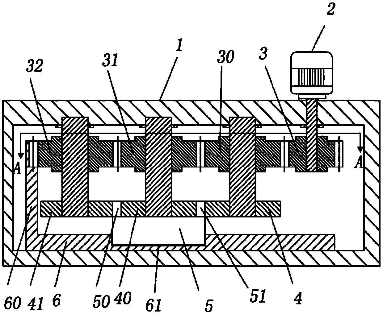
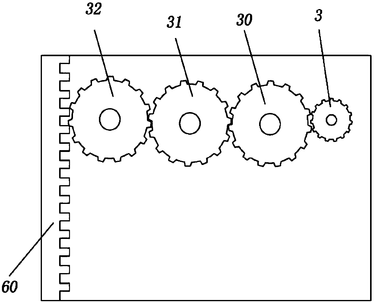
[0021] The reference signs in the accompanying drawings include: frame 1, motor 2, transmission wheel 3, right gear 30, central gear 31, left gear 32, right squeeze wheel 4, center squeeze wheel 40, left squeeze wheel 41 , Transformer body 5, left column pin 50, right column pin 51, support plate 6, limit bar 60, groove 61.

[0022] The embodiment is basically as attached figure 1 Shown: The manufacturing equipment of electronic components, including frame 1, motor 2, power mechanism, straightening mechanism and transmission mechanism. The longitudinal section of the bracket is in the shape of a zigzag.

[0023] The power mechanism comprises transmission wheel 3, right gear 30, central gear 31 and left gear 32 meshed successively, and the output shaft of motor 2 is connected with transmission wheel 3; The diameters of right gear 30, central gear 31 and left gear 32 are equal, so that the right ...


PUM


Abstract

The invention belongs to the technical field of electronic components and particularly relates to manufacturing equipment of electronic components. The manufacturing equipment comprises a rack, a motor, a power mechanism, a straightening mechanism and a transferring mechanism, the power mechanism comprises a transmission gear, a right gear, a center gear and a left gear which are engaged sequentially, and an output shaft of the motor is connected with the transmission gear. The straightening mechanism comprises a right squeezing wheel, a center squeezing wheel and a left squeezing wheel, and the transferring mechanism comprises a limiting strip and a supporting plate for supporting a transformer. One end of the limiting strip is connected with the supporting plate, engaged teeth are arranged at the other end of the limiting strip, the limiting strip is engaged with the left gear through the engaged teeth, and the supporting plate and a support are slidably connected. By adopting the technical scheme, the situation that in straightening, pins are pulled out or scratched, or soldering tin is damaged can be effectively prevented, meanwhile the straightening efficiency is improved, andthe labor intensity is reduced.

Description

technical field [0001] The invention belongs to the technical field of electronic components, and in particular relates to a manufacturing equipment of electronic components. Background technique [0002] Electronic components include transformers, tubes, radiators, etc. The transformer is a device that uses the principle of electromagnetic induction to change the AC voltage. Generally speaking, the transformer structure includes a transformer body and pins connected to the bottom of the transformer body. The pins and the transformer body are connected by solder. The number of pins depends on the specific needs of use. The maximum number of pins in the application is 8, including the left column of pins and the right column of pins. Each column includes 4 pins, and the 4 pins are equidistantly distributed. [0003] The production process of transformers includes winding, taping, wiring, primary soldering, assembly, testing, copper-clad tape, dipping, baking, secondary solde...

Claims


Application Information

Patent Timeline
Patent Type & Authority Patents(China)
IPC IPC(8): B21F1/02H01F27/29H01F41/00
CPCB21F1/02H01F27/29H01F41/00
Inventor 佘加旭
Owner 威海市多益电子有限公司
Why Eureka
Try Eureka