Raid clamping mechanism

A clamping mechanism, fast technology, applied in the direction of clamping, metal processing machinery parts, support, etc., can solve the problems of high labor intensity, high labor cost, inconvenient disassembly and assembly, etc., to reduce labor intensity and flexible use , the effect of convenient work

Pending Publication Date: 2018-04-06
YULIN CHUANDI MACHINERY MFG
View PDF0 Cites 2 Cited by
  • Summary
  • Abstract
  • Description
  • Claims
  • Application Information

AI Technical Summary

Problems solved by technology

[0002] At present, when drilling the square parts of the excavator parts, it needs to be clamped individually for drilling, the processing efficiency is low, and manual clamping is required when clamping, which is inconvenient to disassemble and assemble, and the labor intensity of the workers is high. high cost

Method used


Image

  • Raid clamping mechanism
  • Raid clamping mechanism

Examples


Embodiment Construction

[0018] The specific embodiments of the present invention will be described in detail below with reference to the accompanying drawings, but it should be understood that the protection scope of the present invention is not limited by the specific embodiments.

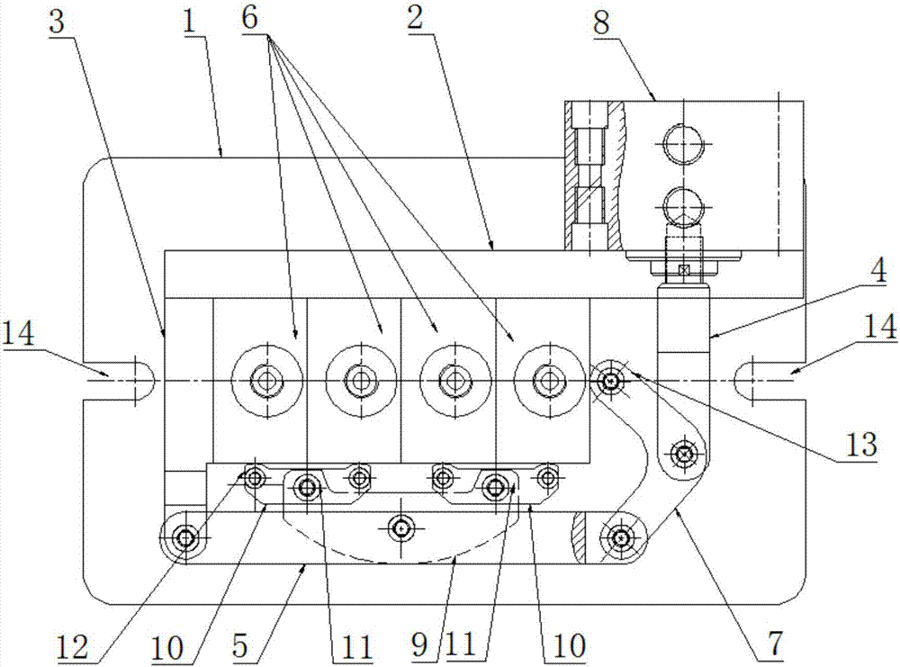
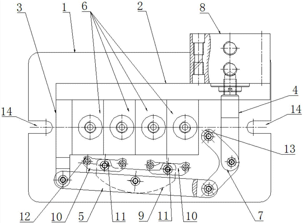
[0019] The specific implementation of the present invention is as follows: Figure 1-2 As shown, a quick clamping mechanism includes a support plate 1, such as figure 1 As shown, the support plate 1 can be divided into four directions: left, right, front, and rear. The support plate 1 is vertically protruding with a first limiting plate 2 and a first limiting plate that can be adapted to the front and left ends of the workpiece 6 respectively. Two limit plates 3, the second limit plate 3 is hinged with a rocker 5 that can rotate to match the rear surface of the workpiece 6, and the rocker 5 is hinged with a connecting rod that can rotate against the right end surface of the workpiece 6 7. The first limit plate 2 is provided...


PUM


Abstract

The invention discloses a quick clamping mechanism, which includes a support plate, on which a first limit plate and a second limit plate are vertically protruded and respectively adapted to the front end surface and the left end surface of a workpiece. A rocker that can rotate and adapt to the rear end surface of the workpiece is hinged on the second limiting plate, and a connecting rod that can rotate and offset the right end surface of the workpiece is hinged on the rocker. A driving device hinged with the connecting rod is provided on the plate, and a rotatable floating and pressing mechanism adapted to the rear end surface of the workpiece is provided on the inner side of the rocker. The clamping and positioning device of the present invention is accurate and stable in positioning, fast in positioning, stable in drilling, and helps to improve machining accuracy; it is convenient in material selection, and convenient and simple in manufacture.

Description

Technical field [0001] The invention relates to the technical field of excavator component processing, more specifically, it relates to a quick clamping mechanism. Background technique [0002] At present, when drilling the square parts of excavator parts, they need to be clamped individually for drilling. The processing efficiency is low, and manual clamping is required during clamping, which is inconvenient for disassembly and assembly, and the labor intensity of workers is high. high cost. Summary of the invention [0003] The technical problem to be solved by the present invention is to address the above-mentioned shortcomings of the prior art. The purpose of the present invention is to provide a fast clamping mechanism with fast positioning and stable drilling. [0004] In order to achieve the above objective, the present invention provides a quick clamping mechanism, including a support plate, the support plate is vertically protruding with a first limit plate and a second li...

Claims


Application Information

Patent Timeline
Patent Type & Authority Applications(China)
IPC IPC(8): B23Q3/06B23B47/00
CPCB23Q3/061B23B47/00
Inventor 陈业敏黎志
Owner YULIN CHUANDI MACHINERY MFG
Why Eureka
Try Eureka