Self-centered side collision preventing bearing

A kind of middle-proof and bearing technology, applied in the direction of bearing components, shafts and bearings, bearing unloading, etc., can solve the problems of deformation, detachment and increased resistance of rolling groove or ball 3, so as to reduce friction, avoid contact, improve The effect of impact resistance

Inactive Publication Date: 2018-04-06
郑帆
View PDF1 Cites 0 Cited by
  • Summary
  • Abstract
  • Description
  • Claims
  • Application Information

AI Technical Summary

Problems solved by technology

[0005] 1. The anti-shock structure is set on one side, that is, the bearing can only prevent side impact force on one side, and the opposite direction will still cause the entire bearing inner ring 2 and bearing outer ring 1 to separate
[0006] 2. When hitting the base 5, the inner ring 2 will be slightly dislocated relative to the outer ring 1, causing the inner ball 3 to be sandwiched between the inner ring 2 and the outer ring 1, and the ball 3 will be clamped inside. Failure to reset in time will easily lead to deformation of the rolling groove or ball 3
[0007] 3. The buffer ball 6 keeps in contact with the side wall of the outer ring, and the friction makes the resistance increase

Method used


Image

  • Self-centered side collision preventing bearing
  • Self-centered side collision preventing bearing
  • Self-centered side collision preventing bearing

Examples


Embodiment 1

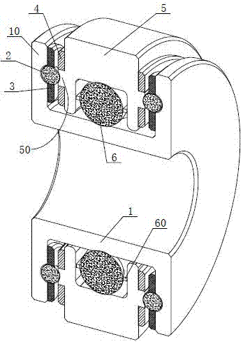
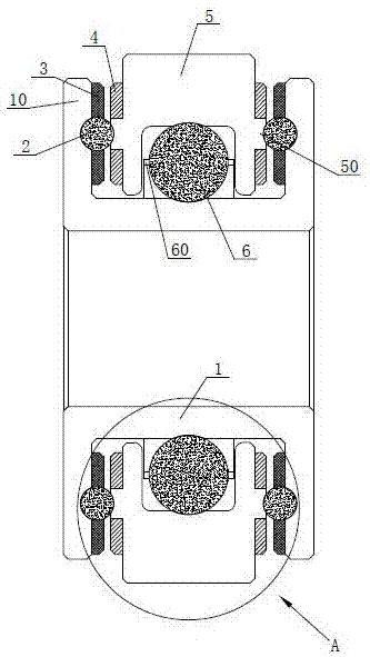
[0033] Such as Figure 5 The shown self-centering anti-side impact bearing includes inner ball 6, outer ring 5, inner magnetic ring 4, outer magnetic block 3, outer ball 2 and inner ring 1 from the inside to both sides (in order to better see the position relationship, the outer ring 5 and the inner ring 1 are all cut from the middle in the figure).

[0034] A cage 60 is provided on the outside of the inner ball 6 for maintaining the distance between the balls.

[0035] Such as Figure 4 As shown, an inner rolling groove is provided inside the outer ring 5 to cooperate with the inner ball 6 and press the inner ball 6 against the outer surface of the inner ring 1 .

[0036] Two sidewalls of the outer ring 5 are provided with protruding rings 50 protruding from the surface of the side walls of the outer ring 5 , and the protruding rings 50 are provided with inwardly recessed outer rolling grooves 51 . The outer ring 5 in this embodiment is made of stainless steel, and the pro...

Embodiment 2

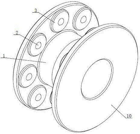
[0045]Such as Figure 6 As shown, this embodiment is based on Embodiment 1, and integrates all the outer magnetic blocks 3 into a whole. The outer magnetic block 3 in this embodiment is annular, and the outer magnetic block 3 surrounds the inner ring 1 and is connected to the inner ring Circle 1 is set concentrically.

[0046] The outer magnetic block 3 is a structure of a whole magnetic ring. There are multiple holes on the magnetic ring for the outer ball 2 to be exposed. The advantage is that it is easy to install and can provide greater magnetic repulsion. However, when assembling and disassembling, it needs Overall disassembly.


PUM


Abstract

The invention discloses a self-centering anti-side impact bearing, which comprises balls, an inner ring and an outer ring. The inner ring is provided with an impact wall extending toward the side wall of the outer ring. An anti-collision mechanism is provided between the wall and the side wall of the outer ring. The anti-collision mechanism includes a slot, an outer rolling groove, an outer ball and an outer magnetic block. The outer ball is embedded between the slot and the outer magnetic block. There are holes for the outer ball to be exposed, and the two side walls of the outer ring are equipped with anti-collision mechanisms. The side walls of the outer ring are provided with an inner magnetic ring, and the outer magnetic block is a magnetic piece that is magnetically attracted and repelled by the inner magnetic ring. There is a gap between the outer rolling groove and the outer ball, and the outer ball is made of non-magnetic adsorption material. By adding mutually repulsive magnetic parts in the anti-collision mechanism, it is used to provide sufficient repulsion for the reset of the inner ring and the outer ring, to prevent the outer ball from contacting the outer rolling groove, and to reduce the friction in the anti-collision mechanism; secondly, it can be used for The inner and outer rings are reset, so that the inner ball can be accurately located in the inner rolling groove, so as to avoid the wear and deformation of the inner ball or rolling groove.

Description

technical field [0001] The invention relates to a bearing, in particular to a self-centering anti-side impact bearing. Background technique [0002] Common bearings in the market generally have the same problem, that is, the bearing cannot bear the axial pressure. When the axial load exceeds the bearing capacity of the bearing, the bearing will collapse, posing serious safety hazards and easily causing major accidents. [0003] At present, the Chinese patent No. 201420441003.4 discloses a stainless steel bearing that can withstand axial impact force. The impact-resistant structure includes a buffer ball and a circular groove, the circular groove is located on the upper end surface, the buffer ball fits with the circular groove, and 1 / 2 to 1 / 4 of the volume of the buffer ball is placed outside the circular groove. Buffer balls and circular grooves are used to withstand axial impact, reduce friction caused by axial loads, and prevent bearings from suddenly stalling. [0004]...

Claims


Application Information

Patent Timeline
Patent Type & Authority Applications(China)
IPC IPC(8): F16C33/58F16C39/06
CPCF16C33/583F16C39/063
Inventor 郑帆
Owner 郑帆
Why Eureka
Try Eureka