
Air-core coil winding equipment

A technology of hollow coils and winding equipment, which is applied in the manufacture of electrical components, inductors/transformers/magnets, circuits, etc., which can solve problems such as low production efficiency, high energy consumption, and burns, and achieve energy-saving design, reduce processing difficulty, and reduce cost effect

Pending Publication Date: 2018-04-06
TANAC AUTOMATION
View PDF1 Cites 0 Cited by
  • Summary
  • Abstract
  • Description
  • Claims
  • Application Information

AI Technical Summary

Problems solved by technology

[0003] The above-mentioned heating method consumes a lot of energy and is prone to burn accidents
[0004] Secondly, the existing air-core c

Method used


Image

  • Air-core coil winding equipment
  • Air-core coil winding equipment
  • Air-core coil winding equipment

Examples


Example Embodiment

[0114] Example one

[0115] Such as Figure 26 As shown, the hollow coil winding equipment includes a frame 1 on which a turntable 2 is provided, and the turntable 2 is connected with a turntable drive mechanism. The turntable drive mechanism includes any one of belt drive and gear drive. Turntable 2 rotates clockwise.

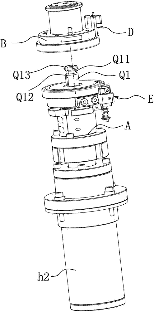
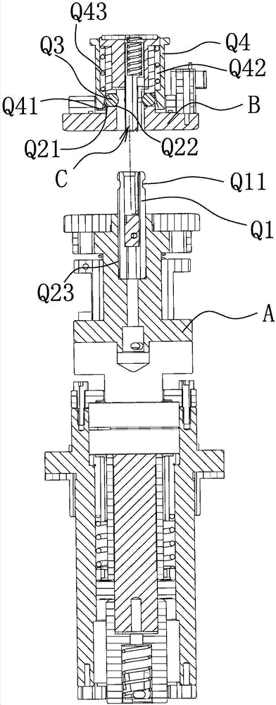
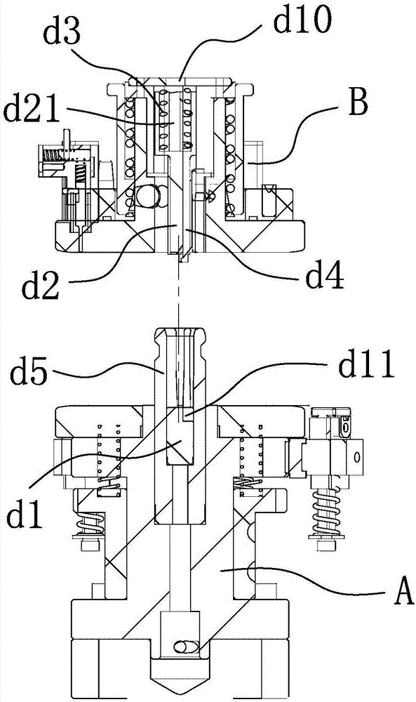
[0116] Such as Figure 1-2 , Picture 20 , Figure 26 with Figure 41-42 As shown, the frame 1 is provided with a wire passing mechanism 3 located on the periphery of the turntable 2 and capable of arranging a number of enameled wires horizontally and able to close the plurality of enameled wires side by side, and a plurality of lower jigs distributed in a circle are provided on the turntable 2 A. Each lower jig A is connected to the upper jig B through the jig clutch mechanism, and an inner wire that can clamp and pierce the hollow coil inner wire is set between the upper jig B and the lower jig A The head clamping and piercing mechanism C is provided on the out...

Example Embodiment

[0249] Example two

[0250] Such as Figure 26 As shown, the structure and principle of this embodiment are basically the same as those of the first embodiment, so I won’t repeat them here, and the difference lies in

[0251] The inner thread head clamping and piercing mechanism C provided on the frame includes any one of a ceramic heating rod j8 and a laser peeling device p2. That is, before entering the jig drive mechanism, the enameled wire is peeled off from the wire end.


PUM


Abstract

The invention relates to air-core coil winding equipment. The air-core coil winding equipment comprises a rack, wherein a rotary table is arranged on the rack, a coil passing mechanism which is arranged at the periphery of the rotary table, can horizontally arrange a plurality of enameled wires and also can cling a plurality of enameled wires side by side is arranged on the rack, a plurality of circumferentially distributed lower jigs are arranged on the rotary table, each lower jig is connected with an upper jig by virtue of a jig clutch mechanism, an internal coil head clamping and puncturing mechanism which can clamp and puncture an internal coil head of an air-core coil is arranged between the upper jigs and the lower jigs or on the rack, an external coil head clamping and puncturing mechanism which can clamp and puncture an external coil head of the air-core coil is arranged on the lower jigs or upper jigs, a jig driving mechanism and a coil energizing mechanism which are sequentially distributed along the circumference of the rotary table are arranged on the rack, and when the rotary table rotates the lower jigs and the upper jigs which are mutually matched to a position of the jig driving mechanism, the jig driving mechanism drives the lower jigs and the upper jigs to carry out winding.

Description

technical field [0001] The invention belongs to the technical field of winding equipment, in particular to an air-core coil winding equipment. Background technique [0002] The current winding machine, when the coil winding is completed, generally heats the entire mold. After the mold is heated, the coil is heated. The insulating layer of the enameled wire of the heated coil is melted to connect the inner and outer rings together. . [0003] The above-mentioned heating method consumes a lot of energy and is prone to scald accidents. [0004] Secondly, the existing air-core coils are all an enameled wire, and when winding one air-core coil, it needs to be wound with N turns, and the production efficiency is low. [0005] In order to improve the above-mentioned technical problems, for example, a Chinese patent discloses a winding fixture, application number 201520734127.6, which includes a winding fixing plate seat with a first surface and a second surface arranged in parall...

Claims


Application Information

Patent Timeline
IPC IPC(8): H01F41/066H01F41/082H01F41/098
CPCH01F41/066H01F41/082H01F41/098
Inventor 李国锋范建良冯丙穆周理
Owner TANAC AUTOMATION
Learn More