Spray arm and cleaning machine

A spray arm and spray hole technology, applied in the field of machinery, can solve the problems of complex connection structure, manufacturing, assembly, and cost disadvantages of the spray arm or spray arm, and achieve a simple structure, low cost, and few parts used Effect

Pending Publication Date: 2018-04-13
NINGBO OULIN IND CO LTD
View PDF0 Cites 8 Cited by
  • Summary
  • Abstract
  • Description
  • Claims
  • Application Information

AI Technical Summary

Problems solved by technology

[0002] The spray arm or the connection structure of the spray arm in the existing dishwasher is relatively complicated, and multiple parts need to be used together, which has considerable disadvantages in manufacturing, assembly, and cost

Method used


Image

  • Spray arm and cleaning machine
  • Spray arm and cleaning machine
  • Spray arm and cleaning machine

Examples


Embodiment Construction

[0021] The following are specific embodiments of the present invention and the accompanying drawings to further describe the technical solutions of the present invention, but the present invention is not limited to these embodiments.

[0022] Combine below Figure 1 to Figure 4 The technical solutions provided by the present invention are described in more detail.

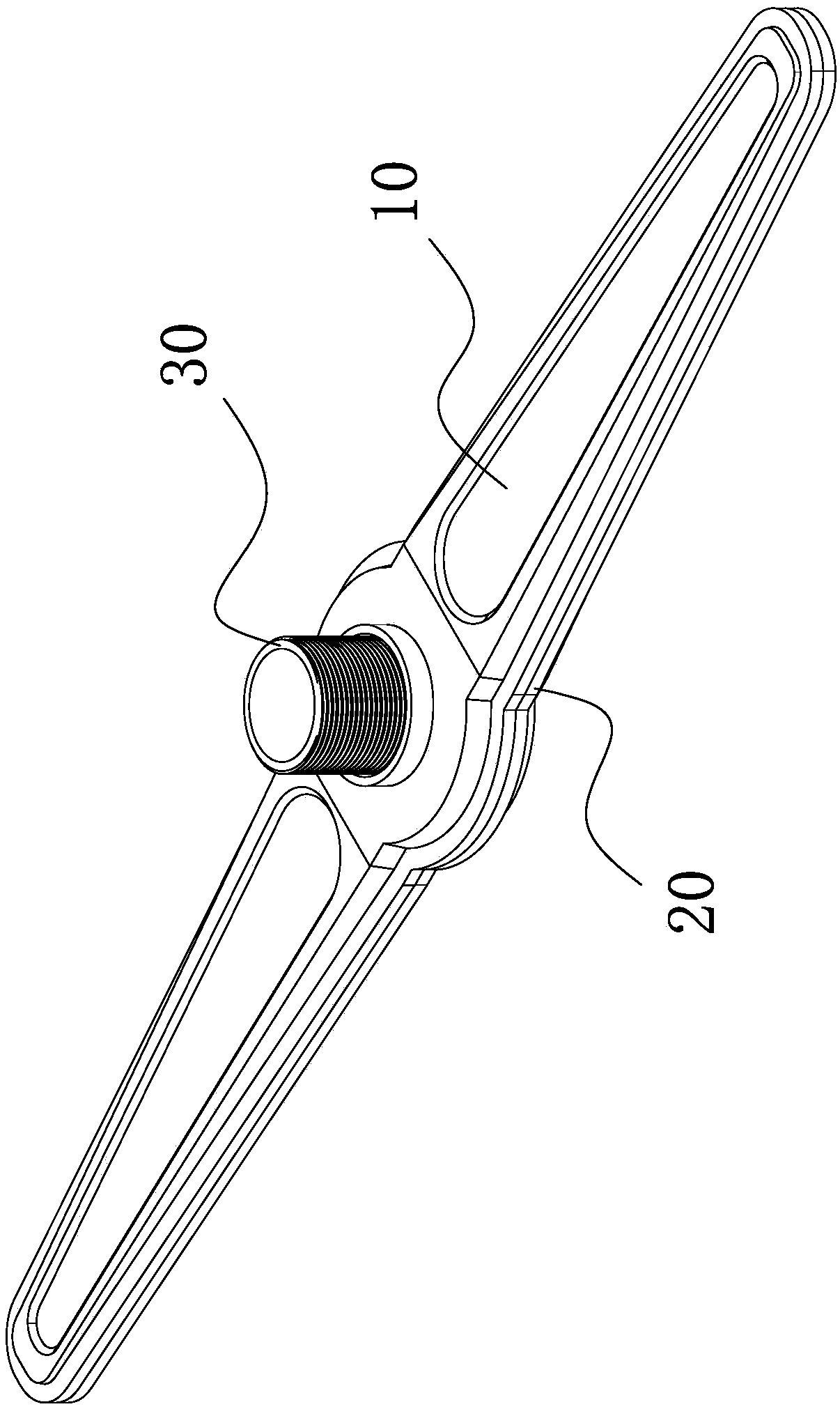
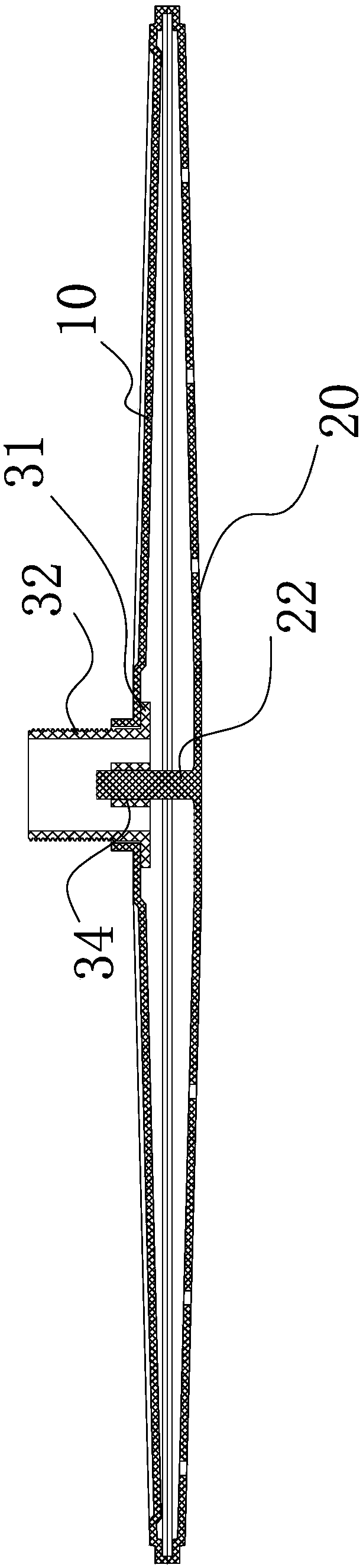
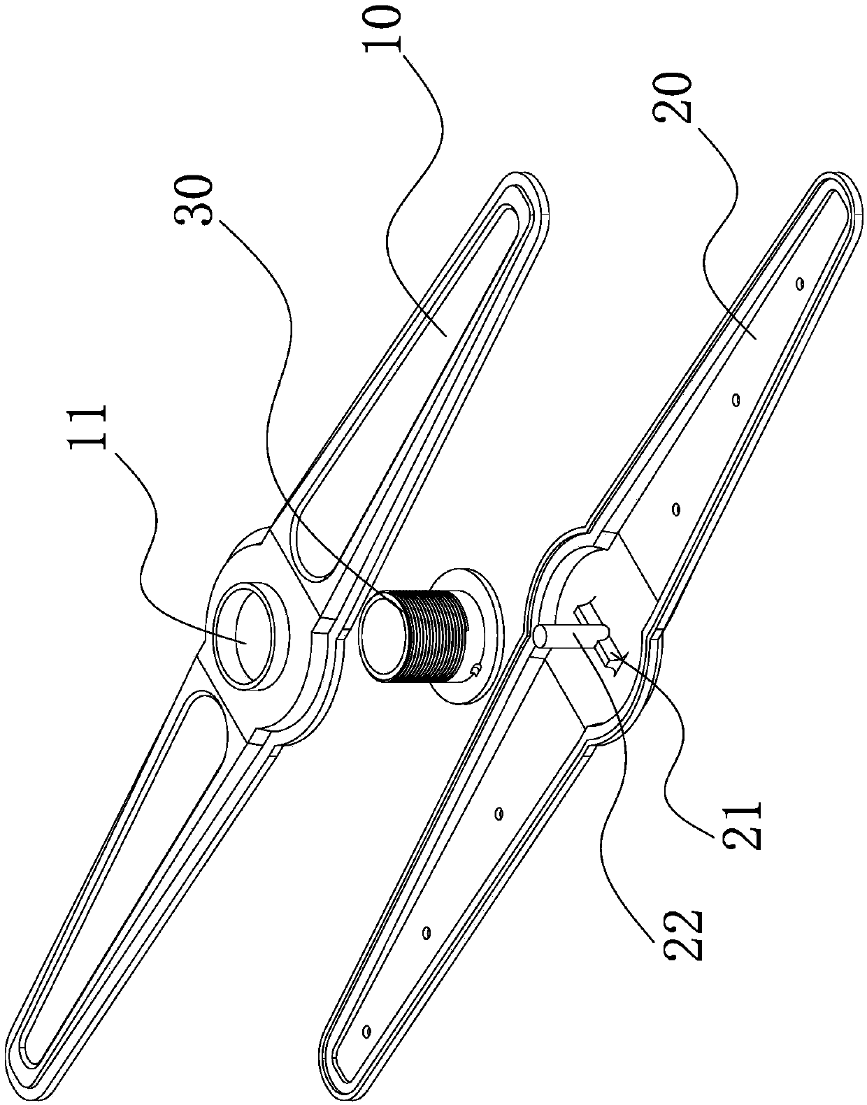
[0023] like Figure 1 to Figure 4 Shown, this spray arm spray arm includes:

[0024] The upper part 10 of the spray arm is provided with a through hole 11 in the middle;

[0025] The lower part 20 of the spray arm, the middle part is provided with a protrusion 21, and the lower part 20 of the spray arm is provided with a spray hole;

[0026] The connecting piece 30 includes a wider connecting part 31 and a narrower fixing part 32, the connecting part 31 is located between the upper part 10 of the spray arm and the lower part 20 of the spray arm, and the fixing part 32 passes through the spraying The through hol...


PUM


Abstract

The invention provides a spray arm, comprising: an upper part of the spray arm, with a through hole in the middle; a lower part of the spray arm, with a protrusion in the middle, and a spray hole in the lower part of the spray arm The connecting piece includes a wider connecting portion and a narrower fixing portion, the connecting portion is located between the upper part of the spray arm and the lower part of the spray arm, and the fixing part passes through the through hole of the upper part of the spray arm , and the bottom of the connecting part is provided with a card slot adapted to the protrusion. The spray arm has the advantages of simple structure and convenient operation.

Description

technical field [0001] The invention belongs to the technical field of machinery, and relates to a spray arm and a cleaning machine. Background technique [0002] The spray arm or the connection structure of the spray arm in the existing dishwasher is relatively complex, and requires multiple components to be used together, which has considerable disadvantages in manufacturing, assembly, and cost. The present invention designs a spray arm with the characteristics of simple structure, few used parts and low cost. SUMMARY OF THE INVENTION [0003] The purpose of the present invention is to solve the above-mentioned problems in the prior art, and propose a spray arm with a simple structure and convenient operation. [0004] The object of the present invention can be achieved through the following technical solutions: a spray arm, comprising: [0005] The upper part of the spray arm is provided with a through hole in the middle; [0006] The lower part of the spray arm, the...

Claims


Application Information

Patent Timeline
Patent Type & Authority Applications(China)
IPC IPC(8): A47L15/22A47L15/42
CPCA47L15/22A47L15/428
Inventor 徐剑光王文龙徐明
Owner NINGBO OULIN IND CO LTD
Why Eureka
Try Eureka