
Automatic welding device for special reinforcement cage seam welder

An automatic welding and reinforcement cage technology, which is applied in applications, grinding machines, household appliances, etc., can solve the problems of manual cutting of longitudinal reinforcement, affecting the welding effect, rusting and deformation of longitudinal reinforcement, etc., and achieves the effect of improving quality and saving manpower

Inactive Publication Date: 2018-04-13
泰州市春为强通用机械有限公司
View PDF0 Cites 8 Cited by
  • Summary
  • Abstract
  • Description
  • Claims
  • Application Information

AI Technical Summary

Problems solved by technology

[0005] Aiming at the deficiencies of the prior art, the present invention provides a special automatic welding device for steel cage roll welding machine, which solves the problems of manual welding, manual shearing of longitudinal ribs, rusting and deformation of longitudinal ribs, etc. that affect the welding effect

Method used


Image

  • Automatic welding device for special reinforcement cage seam welder
  • Automatic welding device for special reinforcement cage seam welder
  • Automatic welding device for special reinforcement cage seam welder

Examples


Embodiment Construction

[0022] The following will clearly and completely describe the technical solutions in the embodiments of the present invention with reference to the accompanying drawings in the embodiments of the present invention. Obviously, the described embodiments are only some, not all, embodiments of the present invention. Based on the embodiments of the present invention, all other embodiments obtained by persons of ordinary skill in the art without making creative efforts belong to the protection scope of the present invention.

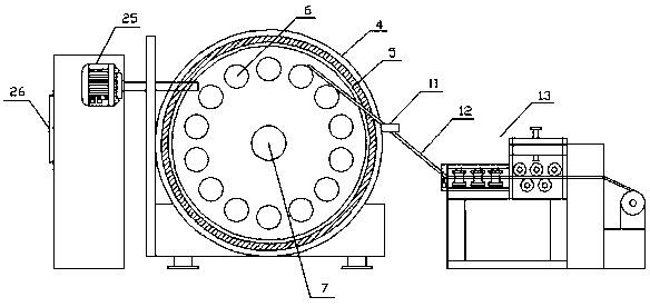
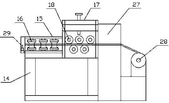
[0023] see Figure 1-3 , the present invention provides a technical solution: a special automatic welding device for steel cage roll welding machine, including a body 1, a welding torch 2 is arranged in the middle of the upper end of the body 1, and a seam welding device 3 is arranged at the right end of the welding torch 2, and the seam welding device 3 is provided with a turntable 4 inside, and a semiconductor cooling ring 5 is arranged between the turntable...


PUM


Abstract

The invention discloses a special automatic welding device for a steel cage roll welding machine, which includes a machine body, a welding torch is arranged in the middle of the upper end of the machine body, a roll welding device is arranged at the right end of the welding torch, a turntable is arranged inside the roll welding device, and there is a gap between the turntable and the roll welding device There is a semi-conductor cooling ring, a rotating shaft is installed at the center of the turntable, the right end of the rotating shaft is connected to a gear reduction device through a support rod, the traction wheel is slidingly connected to a longitudinal rib, the other end of the longitudinal rib is equipped with a derusting and shaping device, and the left end of the upper surface of the support frame is installed. There is a derusting box, the right end of the derusting box is equipped with a shaping box, the lower end of the left side of the roll welding device is equipped with an automatic unloading rack, the upper surface of the automatic unloading rack is equipped with a conveyor chain, the right end of the conveyor chain is equipped with a traction device, and the automatic unloading rack A hydraulic lifting device is arranged in the middle, and telescopic ejector rods are arranged on the left and right sides of the hydraulic lifting device. The invention relates to the technical field of steel cage roll welding machines. The automatic welding device of the steel cage roll welding machine has achieved the purpose of automatic welding, automatic derusting and shaping of longitudinal bars, and has high welding efficiency.

Description

technical field [0001] The invention relates to the technical field of steel cage roll welding machines, in particular to a special automatic welding device for steel bar cage roll welding machines. Background technique [0002] At present, the method of using the existing reinforcement cage rolling welding machine is as follows: the steel bar after being straightened and cut according to the specified length is inserted into the steel bar of the rolling welding machine, and the steel bar in the steel bar tube is pushed out to form a longitudinal bar through the bar pushing device, and then As the longitudinal ribs evenly distributed on the main plate rotate, the ring ribs contact the longitudinal ribs through the wire guide device, and the overlapping points of the longitudinal ribs and the ring ribs are welded by a relatively fixed welding mechanism. Although the current roll welding machine has realized the function of automatic diameter change, it is no longer necessary ...

Claims


Application Information

Patent Timeline
IPC IPC(8): B21F27/10B21F1/02B21F11/00B24B27/033B24B27/00
CPCB21F27/10B21F1/02B21F11/00B24B27/0076B24B27/033
Inventor 王梅赵锦龙陈自全马云良
Owner 泰州市春为强通用机械有限公司
Learn More