An electronic braking method, vehicle frame, power drive assembly and vehicle

A technology of power drive and electronic braking, which is applied in the field of vehicles, can solve problems such as low product utilization, low braking precision, and increased economic pressure on consumers

Active Publication Date: 2021-02-12
NINEBOT (BEIJING) TECH CO LTD
View PDF8 Cites 0 Cited by
  • Summary
  • Abstract
  • Description
  • Claims
  • Application Information

AI Technical Summary

Problems solved by technology

However, due to safety considerations, the balance bike can only be used as a means of transportation, does not have the characteristics of racing, and the usage scenarios are relatively simple
[0004] Both go-karts and self-balancing cars can only be used by users as single-function models, and the product utilization rate is low. If users want to experience these two models, they must purchase both go-karts and self-balancing cars, which greatly increases Economic pressure on consumers also creates waste of resources
[0005] Based on this, it is necessary to propose a car model to meet the use scenarios of karts and balance cars at the same time. However, when designing this model, the braking function on the car body is mostly based on physical and mechanical brakes, such as disc brakes. Realize the braking function, this braking method is easy to wear the wheel and the braking accuracy is low

Method used


Image

  • An electronic braking method, vehicle frame, power drive assembly and vehicle
  • An electronic braking method, vehicle frame, power drive assembly and vehicle
  • An electronic braking method, vehicle frame, power drive assembly and vehicle

Examples


Embodiment Construction

[0064]In order to understand the characteristics and technical content of the embodiments of the present invention in more detail, the implementation of the embodiments of the present invention will be described in detail below with reference to the accompanying drawings. The attached drawings are for reference and explanation purposes only, and are not used to limit the embodiments of the present invention.

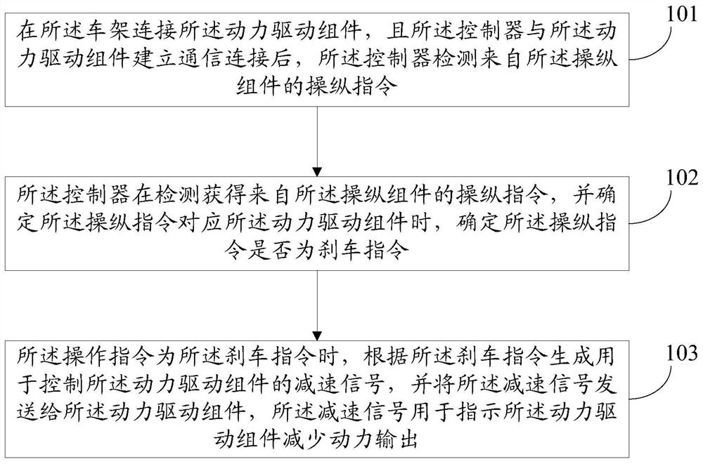
[0065]figure 1 Schematic diagram of the flow of the electronic brake method according to the embodiment of the present inventionFigure one , The electronic braking method in this embodiment is applied to a frame, the frame is used to connect with a power drive assembly, and the frame has a controller and a manipulation assembly for controlling the power drive assembly, such asfigure 1 As shown, the electronic braking method includes the following steps:

[0066]Step 101: After the controller establishes a communication connection with the power drive assembly, the controller obtains...


PUM


Abstract

The invention discloses an electronic braking method, a vehicle frame, a power drive assembly and a vehicle. components. After the controller establishes a communication connection with the power drive component, the controller acquires a manipulation instruction from the manipulation component; when the controller determines that the manipulation command is associated with the power drive component, it determines that the Whether the manipulation instruction is a braking instruction; when the operation instruction is the braking instruction, generate a deceleration signal for controlling the power drive assembly according to the braking instruction, and send the deceleration signal to the power drive assembly, The deceleration signal is used to instruct the power drive assembly to reduce power output.

Description

Technical field[0001]The invention relates to vehicle technology, in particular to an electronic braking method, a frame, a power drive assembly and a vehicle.Background technique[0002]Karts are widely used due to their simple structure, high safety, and extremely high speed characteristics. However, karts can only be used as toys on the track, and have certain requirements on the venue, and the use scene is relatively single.[0003]Balance cars are widely used due to their small size, low energy consumption, ability to relieve road traffic pressure, and high entertainment. However, due to safety considerations, the balance car can only be used as a transportation tool, and does not have racing characteristics, and the use scene is relatively single.[0004]Both karts and balance cars can only be used by users as single-function models, and the product utilization rate is low. If users want to experience these two models, they must purchase both karts and balance cars at the same time,...

Claims


Application Information

Patent Timeline
Patent Type & Authority Patents(China)
IPC IPC(8): B62K13/06B62K13/08B62L1/00B60L7/00
CPCB60L7/00B62K13/06B62K13/08B62L1/00Y02T90/16
Inventor 李星乐
Owner NINEBOT (BEIJING) TECH CO LTD
Why Eureka
Try Eureka