Running water slag remover

A slag remover and flowing water technology, which is used in water supply installations, water conservancy projects, waterway systems, etc., can solve problems such as blockage of drainage pipes, poor drainage, and no running water slag removal device, so as to ensure smooth drainage and maintain smooth drainage. Effect

Inactive Publication Date: 2018-04-13
陈祖炳
View PDF4 Cites 5 Cited by
  • Summary
  • Abstract
  • Description
  • Claims
  • Application Information

AI Technical Summary

Problems solved by technology

At present, rainwater wells on roads in cities and towns in my country are usually covered at the wellhead by a well grate or a perforated well cover. If it enters the rainwater well, it is easy to cause blockage of the well grate, and the rainwater cannot be drained in time, resulting in flooding of streets and roads
After the debris enters the rainwater well and deposits in the rainwater well, it is easy to block the drainage pipe of the rainwater well, resulting in poor drainage.
In view of the problem that existing rainwater wells are prone to blockage, there is no corresponding flowing water slag removal device in the prior art

Method used


Image

  • Running water slag remover
  • Running water slag remover
  • Running water slag remover

Examples


Embodiment 1

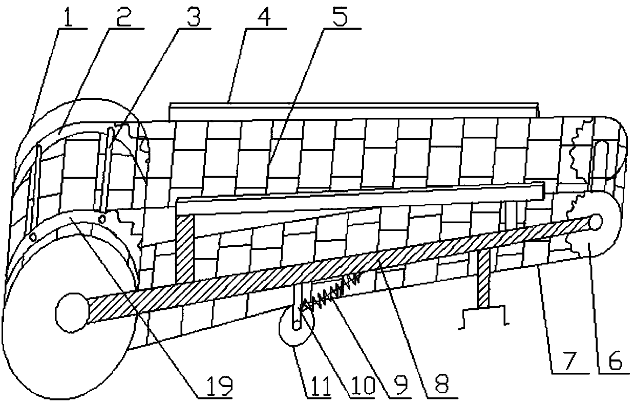
[0035] Such as figure 1 with figure 2 As shown, a flowing water slag remover includes a frame 8, a water wheel 1, a transmission device, and a crawler water grate 5. In the transmission device, two front gear rings are coaxially rotated, and each of the two front gear rings passes through one The transmission chain 7 is connected to a rear gear ring 6, two rear gear rings 6 are coaxially rotatably arranged on the frame 8, the crawler water grate 5 is connected between the two transmission chains 7, and the water wheel 1 is rotatably arranged on the frame 8. It is arranged coaxially with the two front gear rings, and the water wheel 1 drives the crawler water grate 5 to rotate through a transmission device. When water flows down from above the crawler water grate, the water passes through the grate hole on the crawler water grate, and the water passing through the grate hole of the crawler water grate is injected downwards into the water wheel, thereby driving the water wheel to...

Embodiment 2

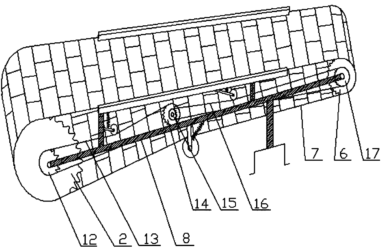
[0046] Such as image 3 with Figure 4 As shown, a flowing water slag remover includes a frame 8, a water wheel 1, a transmission device, and a crawler water grate 5. In the transmission device, two front gear rings are coaxially rotated, and each of the two front gear rings passes through one The transmission chain 7 is connected to a rear gear ring 6, two rear gear rings 6 are coaxially rotatably arranged on the frame 8, the crawler water grate 5 is connected between the two transmission chains 7, and the water wheel 1 is rotatably arranged on the frame 8. It is arranged coaxially with the two front gear rings, and the water wheel 1 drives the crawler water grate 5 to rotate through a transmission device. When water flows down from above the crawler water grate, the water passes through the grate hole on the crawler water grate, and the water passing through the grate hole of the crawler water grate is injected downwards into the water wheel, thereby driving the water wheel to...

Embodiment 3

[0054] A flowing water slag remover, comprising a frame 8, a water wheel 1, a transmission device and a crawler water grate 5. Two front gear rings are arranged coaxially in the transmission device, and each of the two front gear rings passes through a transmission chain 7 A rear gear ring 6 is connected, two rear gear rings 6 are coaxially rotatably arranged on the frame 8, the crawler water grate 5 is connected between the two transmission chains 7, and the water wheel 1 is rotatably arranged on the frame 8 and connected with the two The front gear ring is arranged coaxially, and the water wheel 1 drives the crawler water grate 5 to rotate through the transmission device. When running water flows down from the top of the crawler water grate, the running water passes through the grate hole on the crawler water grate, and the debris in the running water is transported by the crawler water grate to one end of the slag remover, thereby achieving the slag removal of the running wat...


PUM


Abstract

The invention discloses a running water slag remover and relates to the technical field of slag remover. The running water slag remover comprises a rack, a driving device, a transmission actuator anda transporter; the driving device drives the transporter to move by the transmission actuator; sundries of the running water is transported from one end of the slag remover to the other end of the slag remover in the moving process of the transporter. The slag remover can remove the sundries of the running water, and the slag remover can be used for removing slag from rainwater well inflow, fishpond water drainage and water inflow of power plant cooling water.

Description

Technical field [0001] The invention relates to a slag remover, in particular to a flowing water slag remover for removing impurities in flowing water. Background technique [0002] Rainwater wells play an important role in the urban drainage system. They can supplement rainwater underground and drain excess rainwater through drainage pipes, slowing down ground subsidence and preventing roads from being flooded during heavy rains. At present, rainwater wells on urban roads in our country are usually covered by well grate or perforated manhole cover at the wellhead. The well grate is porous or grid structure. In heavy rain, the leaves and other debris on the road surface are gathered on the well grate or with rainwater. Entering the rainwater well will easily cause the grate to be blocked, and rainwater cannot be drained away in time, causing flooding of streets and roads. The debris enters the rainwater well and is deposited in the rainwater well, which easily blocks the drainag...

Claims


Application Information

Patent Timeline
Patent Type & Authority Applications(China)
IPC IPC(8): E02B15/10E03F9/00E03F5/14
CPCE02B15/104E03F5/14E03F9/002
Inventor 陈祖炳
Owner 陈祖炳
Why Eureka
Try Eureka