Self-sensing eddy current type replaceable energy-consuming coupling beam

An eddy current and self-sensing technology, applied in the direction of joists, girders, trusses, etc., can solve the problems of shear damage, lead rubber damper wear, poor accuracy, etc., to achieve real-time monitoring, reduce earthquake damage, The effect of improving comfort

Pending Publication Date: 2018-04-13
TONGJI UNIV
View PDF14 Cites 5 Cited by
  • Summary
  • Abstract
  • Description
  • Claims
  • Application Information

AI Technical Summary

Problems solved by technology

In the design of combined shear walls, coupling beams, as the first line of defense of the seismic system, often suffer severe shear damage under the action of earthquakes exceeding the fortification intensity, which causes great difficulties for post-earthquake repairs
In the field of civil engineering, more accurate sensors such as LVDT for structure control and monitoring are only used under low frequency response conditions and are expensive
Some low-cost but poorly accurate sensors such as accelerometers can only obtain accurate displacement and velocity data through Kalman filtering.
Most of the replaceable energy-dissipative coupling beams that have been developed so far only start to consume energy under moderate and large earthquakes, and remain elastic during small earthquakes and wind vibrations, which cannot meet the structural comfort requirements of high-rise and super high-rise buildings.
And the response monitoring of the existing replaceable coupling beams needs to be observed with the help of additional sensing devices
Most replaceable coupling beams dissipate energy through the metal yielding of the replaceable section or through lead rubber dampers which are susceptible to environmental factors such as temperature and wear due to friction

Method used


Image

  • Self-sensing eddy current type replaceable energy-consuming coupling beam
  • Self-sensing eddy current type replaceable energy-consuming coupling beam
  • Self-sensing eddy current type replaceable energy-consuming coupling beam

Examples


Embodiment

[0027] The purpose of the patent of the present invention is to provide a self-sensing eddy current type replaceable energy-dissipating connecting beam. The connecting beam realizes the safety and comfort of protecting the main body at all stages through the combination of the eddy current damper and the metal energy-dissipating damper, and at the same time achieves The goal of the self-monitoring of the coupling beam during the earthquake is to overcome the shortcomings of the existing replaceable energy-dissipating coupling beams with poor deformation capacity, stability and durability, and to be easy to repair and replace after a major earthquake.

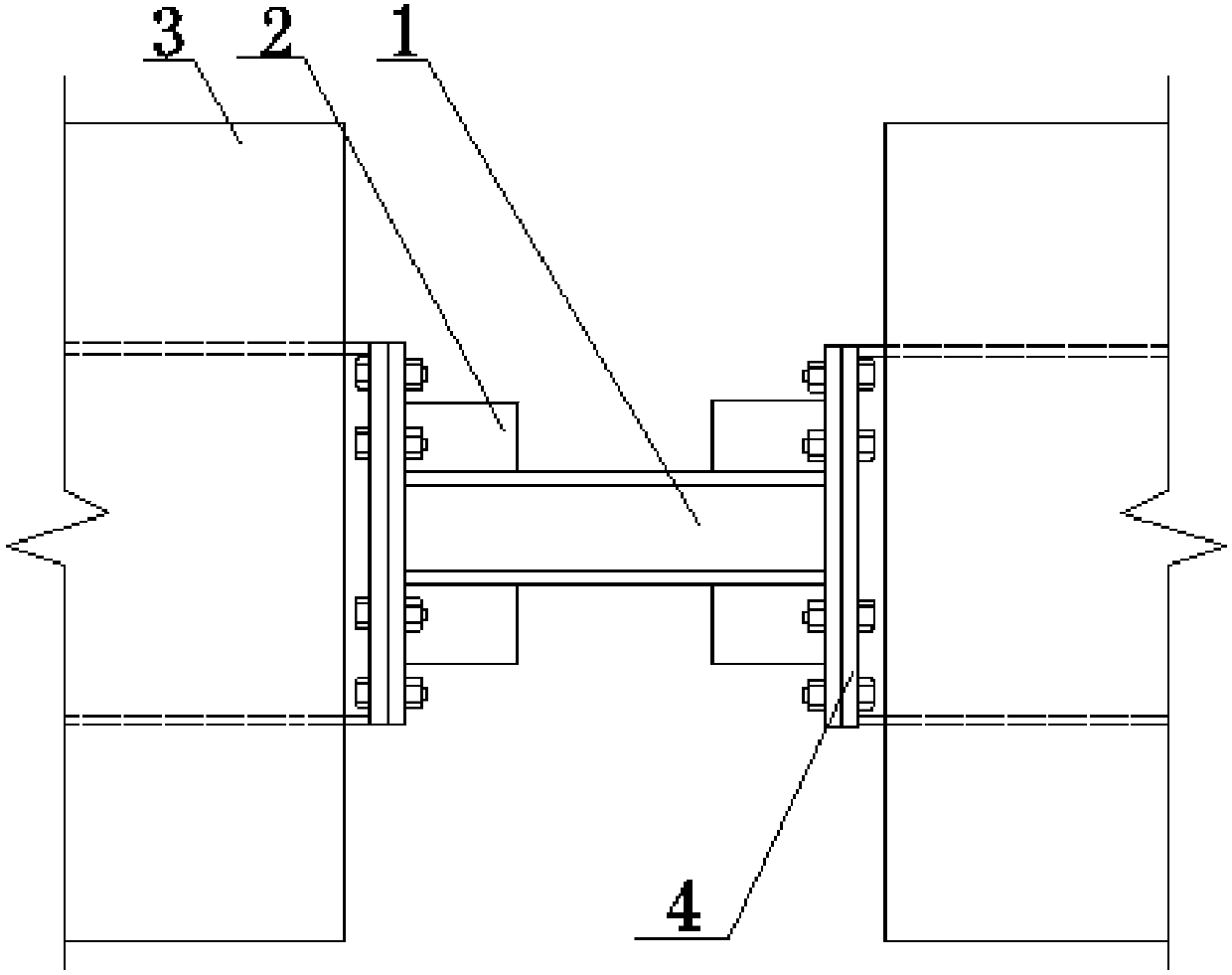
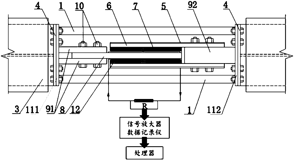
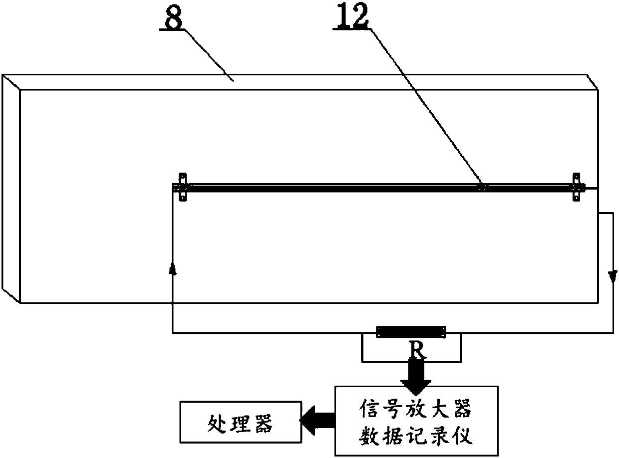
[0028] Such as Figure 1-3 As shown, the present invention provides a self-sensing eddy current replaceable energy-dissipating coupling beam, which consists of a non-energy-dissipating section 3 and a replaceable section. The replaceable section is composed of an eddy current damper 2 and two shaped steel plates 1 connected in p...


PUM


Abstract

The invention relates to a self-sensing eddy current type replaceable energy-consuming coupling beam which is used for sensing a vibration state of a shear wall and dissipating vibration energy. The self-sensing eddy current type replaceable energy-consuming coupling beam comprises a replaceable section and non-energy-dissipation sections arranged at coupling wall columns of the shear wall, the two ends of the replaceable section are fixedly connected with the non-energy-dissipation sections correspondingly, the replaceable section comprises a monitoring circuit, two profile steel plates and eddy current dampers arranged in the two profile steel plates, and the monitoring circuit is connected with the eddy current dampers. Compared with the prior art, the self-sensing eddy current type replaceable energy-consuming coupling beam has the advantages of being capable of self-sensing, adaptive to different vibration strength, frictionless, good in durability, and replaceable and the like.

Description

technical field [0001] The invention relates to the field of anti-seismic and monitoring of civil engineering structures, in particular to a self-sensing eddy current type replaceable energy-dissipating coupling beam. Background technique [0002] Combined shear wall structure is one of the lateral force-resisting systems widely used in high-rise buildings. In the design of combined shear walls, coupling beams, as the first line of defense of the seismic system, often suffer severe shear damage under the action of earthquakes exceeding the fortification intensity, which causes great difficulties for post-earthquake repairs . In the field of civil engineering, more accurate sensors such as LVDTs for structure control and monitoring are only used in low frequency response conditions and are expensive. Some low-cost but poorly accurate sensors such as accelerometers can only obtain accurate displacement and velocity data through Kalman filtering. Most of the replaceable ener...

Claims


Application Information

Patent Timeline
Patent Type & Authority Applications(China)
IPC IPC(8): E04B1/98E04H9/02E04C3/04G01M7/02G01H11/06F16F6/00
CPCF16F6/00G01H11/06G01M7/025E04C3/04E04H9/02E04H9/021
Inventor 单伽锃吴炜超阮康睿
Owner TONGJI UNIV
Why Eureka
Try Eureka