
A Simple Calculation Method for Infill Wall Tendons in Frame Structures

A technology of frame structure and calculation method, which is applied to building components, building types, buildings, etc., can solve the problems of increased engineering workload, waste of tie bars, and too many tie bars, so as to reduce the workload of drilling and increase the economy. Efficient, easy-to-use effects

Active Publication Date: 2019-07-16
ECONOMIC TECH RES INST OF STATE GRID HENAN ELECTRIC POWER +2
View PDF4 Cites 0 Cited by
  • Summary
  • Abstract
  • Description
  • Claims
  • Application Information

AI Technical Summary

Problems solved by technology

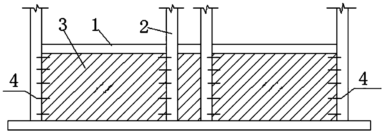
This leads to the fact that according to the existing tie reinforcement arrangement method, when the seismic calculation is carried out, even if the building as a whole meets the seismic requirements, the seismic capacity of the bottom floor will actually be lower than the seismic requirements, and the seismic capacity of the top floors will be higher than the seismic requirements. It not only makes too many tie bars installed on the top floor, which increases the engineering workload and wastes the tie bars, but also makes it easy for the actual seismic level of the bottom floor of the building to fail to meet the predetermined requirements.

Method used


Image

  • A Simple Calculation Method for Infill Wall Tendons in Frame Structures
  • A Simple Calculation Method for Infill Wall Tendons in Frame Structures
  • A Simple Calculation Method for Infill Wall Tendons in Frame Structures

Examples


Embodiment

[0036] Embodiment, a kind of simple calculation method that is used for frame structure filling wall tie reinforcement, it specifically includes the following content:

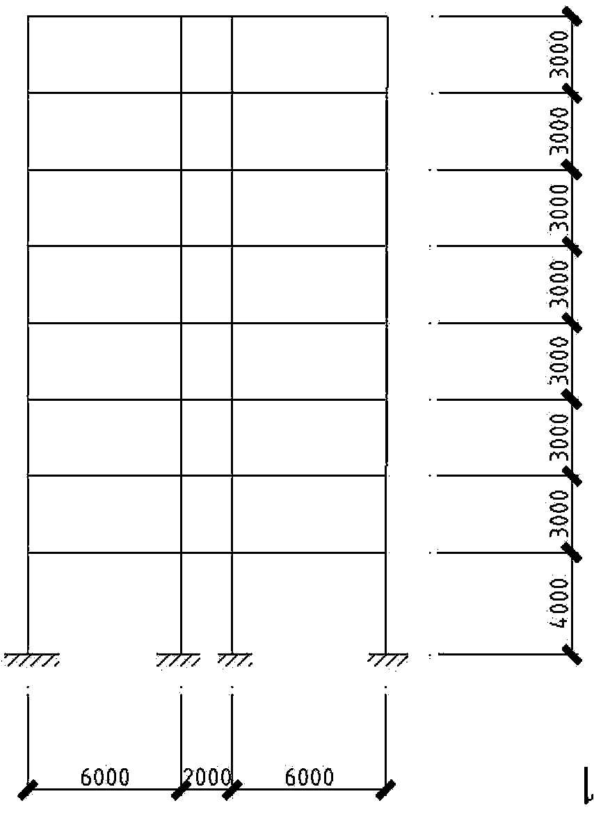
[0037] 1. Calculation of interstory seismic shear force V r (r=1, 2, 3...);

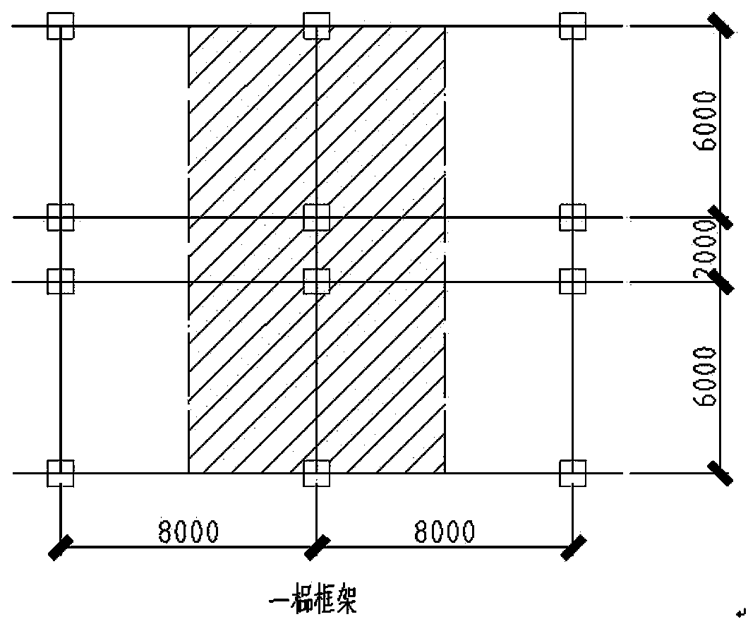
[0038] 2. Determine the number of wall segments that participate in resisting horizontal seismic shear force ω

[0039] 3. Determine the seismic shear force V that can be resisted by all wall sections between stories ω ;

[0040] 4. Determine the remaining seismic shear force of the rth floor (which the frame column should bear and be transmitted by tie bars); V=V r -V ω ;

[0041] 5. Set the number of layers of tie bars for each vertical seam as n, and arrange 2 bars in each layer;

[0042]6. Trial selection of tie bars, d=6mm, P=8.48kN; d=8mm, P=15.08kN; d=10mm, P=23.56kN; d=12mm, P=33.93kN; where: d is tie The diameter of the bar, P is the tensile bearing capacity of a single tie bar;

[0043] 7. Calculation: Taking V≤2n...


PUM


Abstract

The invention discloses a simple calculating method for lacing bars of a frame structure infilled wall. The simple calculating method comprises the steps that firstly, seismic shear force borne by each layer of a building is calculated, then the number of wall segments of the infilled wall of all the layers which participating in resisting the horizontal seismic shear force is determined, then theseismic shear force capable of being resisted by all the wall segments between the layers is determined, then the remained seismic shear force V of the r layer is determined, the remained seismicshear force V of each layer needs to meet the formula that V is less than or equal to 2n*omega*P, taking the formula that V is less than or equal to 2n*omega*P as the precondition, the lacing bar design scheme that the using number of the lacing bars is the least, and the layer-to-layer space between the lacing bars is not more than 1000 mm according to the design standard requirement of masonryis selected, and the type of the selected lacing bars is determined. The simple calculating method for the lacing bars of the frame structure infilled wall overthrows the arrangement form that the lacing bars are arranged according to the structure in a traditional design idea, seriously-unreasonable traditional arrangement of the lacing bars is proved, meanwhile, traditional convention that the lacing bars are not required to be calculated is abandoned, the lacing bars are required to be determined through simple calculation, it is ensured that the infilled wall does not collapse under frequently occurred earthquakes, the drilling work amount of embedded steel bars is greatly reduced, and economic benefits are increased.

Description

technical field [0001] The invention belongs to the technical field of frame structure design, and in particular relates to a simple and convenient calculation method for filling wall tie bars of frame structures. Background technique [0002] At present, in the domestic aseismic design of frame structures, infill walls, as non-structural components, generally do not participate in the force analysis of the overall structure, but are only added as loads to the main structure. Appropriate discounts were made. The layout of the tension bars in the filled wall is only in accordance with the requirements of the code, from the bottom to the top. [0003] However, previous earthquake damages and existing research data show that under earthquake action, the infill wall first resists the seismic shear force. When the wall cracks and loses its lateral stiffness, the infill wall withdraws from work and the frame bears the seismic shear force. The tie bars become the link between the...

Claims


Application Information

Patent Timeline
Patent Type & Authority Patents(China)
IPC IPC(8): E04B1/98E04H9/02
CPCE04H9/02E04H9/021
Inventor 刘湘莅郭正位黄新中尚守平郭新菊席小娟齐道坤刘存凯胡鑫路晓军梁晟李勇景川肖波杨敏唐旻
Owner ECONOMIC TECH RES INST OF STATE GRID HENAN ELECTRIC POWER
Learn More